

I'm having trouble calming down 2 Tempo Sonics. I'm using Studio 5000 CompactLogix my Raw value is jumping around from 8575.0 to 8755.0 at a rested state they are both behaving the same. Is there a way I can calm this down are make it a little tighter? I've tried the Input Module Config Filter No Luck. Any Help is appreciated Thanks.
You are using an out of date browser. It may not display this or other websites correctly.
You should upgrade or use an alternative browser.
You should upgrade or use an alternative browser.
Input Analog Jittering
- Thread starter Karl362
- Start date
OkiePC
Lifetime Supporting Member
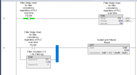
I use a first order filter I Learned from Mickey on this forum years ago. Set it up to operate at a fixed interval on a oneshot and add a percentage of the difference between the raw value and the filtered value each cycle. I normally do this to the mA value before scaling to engineering units, but either is fine.
Here's a screenshot of one I embedded in a scaling AOI:
Just ensure that FC (filter constant) is greater than zero or less than or equal to 1.0. When 1.0, filtering is disabled.
Here's a screenshot of one I embedded in a scaling AOI:
Just ensure that FC (filter constant) is greater than zero or less than or equal to 1.0. When 1.0, filtering is disabled.
Attachments
Mickey
Lifetime Supporting Member
Thanks I'll try this 1st thing in the morning and let you know how it works.I use a first order filter I Learned from Mickey on this forum years ago. Set it up to operate at a fixed interval on a oneshot and add a percentage of the difference between the raw value and the filtered value each cycle. I normally do this to the mA value before scaling to engineering units, but either is fine.
Here's a screenshot of one I embedded in a scaling AOI:
Just ensure that FC (filter constant) is greater than zero or less than or equal to 1.0. When 1.0, filtering is disabled.
Thank youSee pdf for filter.
MaxK
Member

The pf filter is a 1st order low pass filter or 1-st order lag
u = T * (y - y1) / Δt + y
u * Δt + T * y1 = y * (T + Δt)
u * Δt + T * y1 + y1 * Δt - y1 * Δt = y * (T + Δt)
u * Δt - y1 * Δt + y1 *(T + Δt) = y * (T + Δt)
Δt *(u - y1) + y1 *(T + Δt) = y * (T + Δt)
Δt/(T + Δt) *(u - y1) + y1 = y
y = y1 + Δt / (T + Δt) *(u - y1)
u- input
y1- old filtered value
y - new filtered value
@Karl 362 why do you need filtering? You want to see smooth curve? Or it's closed loop?
I hope you realise that the smoother the filtered value is, the more it will lag behind the actual signal.
Tinine
Member

Is this a new installation?
Have you looked for the source of the noise?
Filtering should be a last resort...."They are both behaving the same". Look at cable routing/grounding.
Have you looked for the source of the noise?
Filtering should be a last resort...."They are both behaving the same". Look at cable routing/grounding.
Tinine
Member
From Temposonics instructions:
Instructions for connection
• Use low-resistant twisted pair and shielded cables and connect the shield to ground externally via the controller equipment
.• Keep control and sign leads separate from power cables and sufficiently far away from motor cables, frequency inverters, valve lines, relays, etc
.• Use only connectors with metal housing and connect the shielding to the connector housing.
• Keep the connection surface at both shielding ends as large as possible.
• Keep all non-shielded leads as short as possible.
• Keep the earth connection as short as possible with a large cross section. Avoid ground loops.
• With potential differences between machine and electronics earth connections, no compensating currents are allowed to flow across the cable shielding. Recommendation: Install potential compensating leads with large cross section, or use cables with separate double shielding, and connect only one end of the shield.
• Use only stabilized power supplies in compliance with the specified connecting values
Peter Nachtwey
Member

Do you have an oscilloscope? I would first check the power supply. Other loads can induce noise on the power supply.. Then I would disconnect the long cable and read the signal at the pins on the tempo sonic rod. If there is no noise then the noise is being induce on the cable. Follow the requirements for the cable.
You shouldn't need to filter in software.
You shouldn't need to filter in software.
Yes they both have proper ground and others are on the same card but different types of devices. These Tempos have there on software inside them I'm going to make a phone call today to see whats all involved with that I normal have to get them sent in I'll fill you in when I know more.Is this a new installation?
Have you looked for the source of the noise?
Filtering should be a last resort...."They are both behaving the same". Look at cable routing/grounding.
I use a first order filter I Learned from Mickey on this forum years ago. Set it up to operate at a fixed interval on a oneshot and add a percentage of the difference between the raw value and the filtered value each cycle. I normally do this to the mA value before scaling to engineering units, but either is fine.
Here's a screenshot of one I embedded in a scaling AOI:
Just ensure that FC (filter constant) is greater than zero or less than or equal to 1.0. When 1.0, filtering is disabled.
Attachments

Did find out that the stable North and South Tempo is a SSI. I tried the logic don't know if I actually did it correctly?I use a first order filter I Learned from Mickey on this forum years ago. Set it up to operate at a fixed interval on a oneshot and add a percentage of the difference between the raw value and the filtered value each cycle. I normally do this to the mA value before scaling to engineering units, but either is fine.
Here's a screenshot of one I embedded in a scaling AOI:
Just ensure that FC (filter constant) is greater than zero or less than or equal to 1.0. When 1.0, filtering is disabled.
Can You better explain this I believe I have something wrong?I use a first order filter I Learned from Mickey on this forum years ago. Set it up to operate at a fixed interval on a oneshot and add a percentage of the difference between the raw value and the filtered value each cycle. I normally do this to the mA value before scaling to engineering units, but either is fine.
Here's a screenshot of one I embedded in a scaling AOI:
Just ensure that FC (filter constant) is greater than zero or less than or equal to 1.0. When 1.0, filtering is disabled.
Mickey
Lifetime Supporting Member
Look at the pdf I posted in post #3 of this thread.Can You better explain this I believe I have something wrong?
OkiePC
Lifetime Supporting Member
It looks like you set the FC (Filter Constant) to 1.0 which disables it. Set it to 0.1 or 0.05 and see how it looks. I recommend setting up a trend with the realtime value and the filtered value on the same scale. That lets you visualize the impact of your filter on both noise and real world process signal changes.
Similar Topics
I cannot add SLC500 analog input tag (I: 8.3) to EZSeries Touch Panel Editor (V 5.3). I used all the listed tag datatype but it all says "Invalid...
- Replies
- 10
- Views
- 283
Hi, I have questions. I have Analog Input that need to put into Ignition Designer. But I don't know how to put?
- Replies
- 1
- Views
- 131
Omron AD081-V1 Analog Input Card
Offset & Gain Adjustment
Entering Adjustment Mode
1. Set the input card in adjustment mode (Turn ON Dip SW No-1)...
- Replies
- 0
- Views
- 104
Why AMIo800 Analog input module's I/O LED is Lighting up Red?
Checked module connections, 4-20ma wires etc but this light is continuously Lighting...
- Replies
- 1
- Views
- 116
In this sample programming, what does U4 mean?
Any assistance would be greatly appreciated.
- Replies
- 8
- Views
- 286