Can't control a temperature zone

TCIG

Member
Join Date
Aug 2002
Posts
57
Hi everyone,

I've got a liquid adhesive dispense valve which needs to be maintained at about 300 degrees F. Its temperature is being controlled in a ControlLogix controller, using RSLogix 5000's PIDE control block. The output of the block is a value between 0 and 1000 which determines the percentage of the time the heater will be turned on. (So if the PIDE output is 630, the heater will be on 63% of the time)

Is that commonly called time-proportioned?

Anyways, the temperature of this valve overshoots by 40 degrees or more sometimes, which is unacceptable. I've got another valve, being controlled by another controller, but set up exactly like this one, that maintains the temperature right at 300 degrees, plus or minus a few tenths of a degree. The logic is exactly the same in both controllers, and the PIDE loop setup and paramaters are exactly the same in both controllers.

I've verified the RTD shows about 100 ohms at ambient temperature, measured from the wires right at the RTD input card. I've swapped the dispense valves so that the one that was being controlled properly is now on the controller that isn't working right - problem wasn't there.

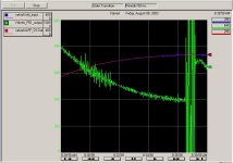
Attached is a screenshot of the trend of the one I can't get to hold 300 degrees F. The red line is the RTD input (run through a lowpass filter, since there was some degree of noise) and the green is the control variable output of the PIDE loop.

Any ideas?
valvea_1.jpg
 
thermal coupling

If overshoot seems to be the problem make sure that the rtd is well mounted and thermally connected to the valve. Maybe use some thermally conductive compound around it?

$0.02
 
If I read your post correctly the green is the PID output which is varying way to much for the amount of temp change. I would check your parameter settings again. I am not familiar with the controllogix PIDE Function Block but I would definitely take a close look at the one you have that works correctly and compare every parameter and time base for the r/min.
 
Where is the heater and where is the sensor?

If the sensor is too far removed from the heater then you will indeed get over-shoot and under-shoot. Your sensor needs to be in the same location relative to the heater as is the case in the system that is working.
 
The heater and the sensor are in very close proximity (both in the dispense valve). As for comparing all the parameters with the controller that does work, I've done that - three times. They're all exactly the same, down to quite a few decimal places on the gains, even.

I'll try removing the filter block and physically reducing the noise somehow.
 
I just tried the controller again, this time after swapping RTD input cards with the controller that was working right. I was hoping that input noise from the card was causing the large fluctuations in the output of the PIDE. Turned out not to be the case - the same controller is still having problems with the other RTD input card.

It basically gets within a few degrees of setpoint temperature without any problems and then just goes crazy. After that, it keeps losing stability every few minutes.

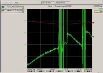
Here's the graph. This one still has the PIDE input coming from the filtered RTD input. I have since taken that out and it hasn't improved.

valvea_2.jpg
 
very short on time ... first let’s experiment and try to eliminate the PID as a possible suspect ...

question: what happens when you put the PID in the manual mode and send out (... let’s just say ...) a rock-steady 50% output for a few minutes?

answer A: I still get some BIG intermittent disturbances of signal “noise” in my input signal.

answer B: The BIG disturbances of input signal “noise” go away and the input just continuously simmers along as a fairly smooth signal.

if your answer is A then the PID does NOT appear to be causing your immediate problem ... don’t mess around with the PID until you get the noise issue corrected ... from where I sit, it looks like the transmitter for the “problem” input might not be properly referenced to “signal ground” ...

... without any problems and then just goes crazy. After that, it keeps losing stability every few minutes.

these are classic symptoms of an analog input signal which is allowed to “float” due to a missing “signal ground reference” ...

double-check the wiring for the “good” signal keeping a close eye out for a ground wire (quite possibly run through something like a 1K ohm resistor) connected to the “low” side of the transmitter’s OUTPUT signal loop ... if you find such a “signal ground reference connection” in the “good” system, is there also a corresponding connection in the “bad” system? ... if these are two-wire transmitters, then any “signal ground reference” wire might be connected to the “low” side of the transmitter’s power source ... are both transmitters served by the same power supply? ... if not, are both power supplies connected exactly the same? ... again, keep a close eye out for any “ground” wires on the power supply output wiring ... also, double-check the “grounding” of the cable shield on the “bad” signal’s wiring ... the shield should usually (I never say “always” but I'm very tempted in this case) be grounded at one end of the cable only ... grounding at both ends (or not even grounding the shield at all) is just asking for trouble ...

if your answer is B then the PID might be causing your problem ... double-check the setup of the PID’s making sure that any “timing” issues are taken care of ... I’m not familiar with the PIDE block setup so I might be out in left field on this one ... but with all other Allen-Bradley PID’s the internally specified "update” time and the timing of the external “trigger” must match precisely or else the Integral action and the Derivative action will be way off from their actual “parameter settings” values ... go back over your programs and pay careful attention to any differences between such things as the “task scan rates” of the “good” and the “bad” controllers ... specifically, even though both PID’s are physically set up the same “parameter-wise”, are they both actually being EXECUTED at exactly the same rate? ...

final thought: thanks for the graphs ... but try setting up the three pens so that the controller output (green) is at the TOP of the list ... that way the input signals (specifically the “raw” unfiltered one) shouldn’t be “overwritten” by the controller output signal ... it would be really nice to know if the blue trace is actually “going crazy” behind all of that green hash ... or if it’s really just simmering along with its “business as usual” background noise level while the PID’s output is freaking out ... of course if we knew the answer to that particular question, then we just might be able to isolate either the PID or the “input signal noise” as the probable cause of the problem ...

hope this helps ... wish I had more time ... offline until Monday ... good luck ...
 
Here's some more charts to look at.

I ran a test (manual control and forced control variable to 50%) on Friday, but forgot to record it. I still saw noise, so I started taking your suggestions and looked for loose or incorrect grounding which might cause my noise. Didn't find anything.

So today I noticed my RTD inputs were not loose, but they had a large part of the wire exposed outside the card's terminals, so I re-terminated them. The first chart below shows my attempt at letting the controller control the temperature zone after re-terminating my RTD at the card. Again, it got noisy as it got near the setpoint.

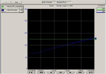
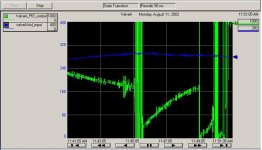
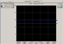
The mext two charts are another manual control test I just finished running. One is a 10 minute window, and the second is a 60 second snapshot. I notice the noise doesn't look so bad when I zoomed in. Is this "normal" fluctuations, or actual noise which could be throwing my PID off?

The 10 minute window makes it look like the noise gets worse as the zone gets hotter. This would seem to indicate I should replace the RTD, except that I've already done that. I've replaced all hardware relating to this zone from the valve (with the RTD and the heater) to the ControlLogix backplane - the valve, the hose (which has the RTD and heater wiring in it) the RTD cable going into the RTD input card, and the RTD input card itself.

Any more ideas? In the meantime, I'll keep looking for a bad grounding.

Thanks!

valvea_4.jpg
 
Oops

Sorry, the above chart was the second one I wanted to post - the 10 minute window for the 50% PID output test.

Here's the chart for the PID controlled run before I forced the output to 50%.

valvea_3.jpg
 
I hate to sound like a broken record but "TUNING"! there is no way that small a change in a temperature variable should generate that large of an error correction! You seem fixated on the noise on the RTD but if tuned correctly a slight amount of noise wouldn't cause such a large swing.
 
I have attempted several tuning procedures, all of which did not work as well as the original settings from the vendor.
 
TCIG,

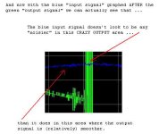
I wouldn’t bet more than about $1.00 but - from where I sit it looks like “input signal noise” is probably NOT causing your problem. Notice that the blue traces (the raw input signals) in all of your graphs are always pretty much just simmering along ... even during those intermittent periods when the PID output signals (the green traces) are going COMPLETELY CRAZY. True, there IS a small amount of fluctuation on the input signal - but nothing that looks radically excessive to me. Have you compared the appearance of this particular input signal to the input signal on the “good” system that you mentioned in an earlier post? Specifically, do the two input signals seem to have about the same amount of “chatter” ... or is the “good” system’s signal much smoother in appearance at all times? Of course I’m just guessing here, but I’ll bet that the “good” one is going to look just about as noisy as the “bad” one.

Again, it does NOT look like there is a significant INCREASE in the “noise” level during those periods where the PID gives you that “wild and crazy” output signal. So now we have to ask ourselves: “If the input signal is running along with its “business as usual” amount of noise ... then what could be making the PID intermittently calculate such a crazy output signal?

The most obvious culprit would seem to be the PID tuning parameters ... but based on what you’ve already posted, the parameters in the “bad” system are set up exactly like the parameters in an identical “good” system. So let’s skip over THAT potential trouble spot - at least for the time being.

The next thing that I’d check would be the PID’s execution time. Specifically is the processor actually ... honestly ... really and truly ... executing the PID at the proper rate? As I said before, I don’t have any experience at all with the ControlLogix PIDE instruction ... but I did take a quick look at the online help for the PIDE and I did find this interesting warning by following the links under the “Timing Mode” section:

Time-based instructions require a constant value for DeltaT in order for the control algorithm to properly calculate the process output. If DeltaT varies, a discontinuity occurs in the process output. The severity of the discontinuity depends on the instruction and range over which DeltaT varies. A discontinuity occurs if:

- the instruction is not executed during a scan

- the instruction is executed multiple times during a task

And just so you don’t miss the point, “a discontinuity ... in the process output” is just a rather polite way of saying “the output can go CRAZY”.

I mentioned the possibility of “timing-scanning-execution-trigger” issues in my earlier post. So far you haven’t told us whether you’ve actually checked for these types of problems. If you haven’t already done so, I’d strongly suggest that you take a careful look at them now. As I said earlier, with ALL of the other Allen-Bradley PID formats, if the PID is not executed on an accurately timed schedule, then the effects of the Integral and the Derivative actions will be significantly altered from the effects called for by their “parameter setting” values. I’d be amazed if the ControlLogix PIDE instruction behaved any differently in this respect. And the section of the online help which I quoted above seems to confirm my suspicions along these lines.

So I’m still not ready to bet anything more than loose pocket change at this point, but right now I’m strongly leaning toward those “task scan rate” types of issues as the most likely culprit. How about checking those out and then let us know what (if anything) you find.

Also - if time allows (but it’s not very likely) I’ll try to experiment with the ControlLogix PIDE instruction sometime this week. Just in case I’m able to pull this off, can you post the parameter setup (specifically the “Timing Mode” settings) that you’re using? If you can do that then I’ll try to base my initial experiments on your particular system as much as possible. Maybe something useful will turn up.

Finally, in the "a picture is worth a thousand words" department:
[attachment]

pide noise.jpg
 
Last edited:

Similar Topics

I have S7 1512C controler for controlling 48 PID temperature loop, the output is PWM. Please I need the best, most efficient way to write the...
Replies
13
Views
604
Hey everyone I'm trynna write a program to a WEST PRO16 temperature controller, but it just won't download the program i made using BlueControl...
Replies
0
Views
750
I am at a loss... I have a pasteurizing system that i need to control product temperature with the speed of the product pump. I currently have a...
Replies
11
Views
2,585
Hello PLC community, I'm looking for advice on a project that I'm going to do for the first time with a PLC (Siemens), the system is to do an...
Replies
7
Views
1,574
I have PID temperature control which will connect to Beckhoff EL4004(0v-10v). How I can program it to let EL4004 to control the temperature?
Replies
7
Views
2,631
Back
Top Bottom