Omron - CJ1M and CAD drawings

alekbeck

Member
Join Date
Mar 2009
Location
Tønsberg
Posts
40
Hi everyone.

I am currently making autocad drawings of a CJ1M with the following components:

CJ1M-CPU11 - ETN
CJ1W-PA205R
CJ1W-AD081
CJ1W-DA041
CJ1W-ID211
CJ1W-OC211

There will be one drawing for each component, showing the powersupply and in- and outputs. This is my first time with a omron product, an i cant find eny manual for digital in- and output components (ID211 , OC211).

Does every component need extra 24VDC powersupply ?

Does enyone have eny example drawings i can use ?
 
Why would you make AutoCad drawings of the CJ1 when they are available on the OMRON website?

Seems like an exercise in futility!
 
Sorry for my bad english. I think you missunderstood me. I ment drawings like the picture below, that shows inputs or outputs.

The picture is a example that got sendt to me from a contact. What i doent understand is the 230V connection. I thought the PS205 would supply all my component with 24VDC.

ScreenShot002.jpg
 
Typically the diagram you attached would be created by the machine builder. The manufacturer may supply dimensional drawings for the hardware.

The PA205 supplies 5vdc and 24vdc to power the cpu and modules internally.

A separate power supply is required to power the devices wired to the modules.

Please take a look at the CJ1 Operation Manual (W393). This should help you to understand how to wire and properly power the I/O modules. All modules are details in this manual.
 
Thanx for the help, that manual helped me alot !

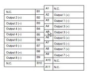
One more question. Where do i connect the 24VDc powersupply to the AD081 and DA081 (see picture below)

ScreenShot003.jpg
 
Those modules are considered "special I/O" modules.

Manual W345 has the all information about the analog modules.
You can find that manual at the same website as the W393 manual.

Hope this will help.
 
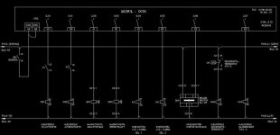
Here is a standard drawing method I use. All inputs in from the left, all outputs out to the right.
I normally use DC powered units and a DC power supply - the Australian Standard symbol is used for the DC power supply.
The PLC is a CP1M type.
Hope this helps.
If you need more let me know.
 
Last edited:
Here are 2 more drawings for the CJ1M. One drawing has a lot of control circuit stuff but also an analogue input card with loop powered transmitters.
The other drawing is fo a 64 bit input card, 64 bit output card, processor etc.
I wire my own plugs and make cables as long as I need to reach doors, adjoining cubicles etc.
This job actually uses a 240 VAC power supply for the processor and a separate 24 VDC power supply for the I/O.
 

Similar Topics

Hi dear . I have a system with cj1m cpu11 etn. previously NT 5z HMI was connected with plc. recently my old HMI got damaged. I want to replace it...
Replies
12
Views
248
hi dear all hope you all are fine I have a problem with my CJ1M cpu11 ETN. it stop communication with PC over ethernet. ETN unit all indications...
Replies
4
Views
169
Hello everyone. I am new when it comes to Omron PLCs. Currently I'm uploading program from CJ1M PLC using CS1W-CIF31 cable only. I connected the...
Replies
2
Views
159
i have been trying to connect to omron cj1m via peripheral port(USB to Serial), but there isn't any sign to show that it has connected, so am...
Replies
0
Views
318
Has anyone encountered an error code 31 on an omron cj1m-cpu12? This error code is not covered in PLC manual.
Replies
1
Views
521
Back
Top Bottom