I am trying to add a RIO adapter to a PLC-5 but am a bit lost on the steps to do this. It is a Allen-Bradley PLC-5/20 1785-L20B processor module in a 1771-A3B1 12 slot chassis and I am trying to connect a Allen Bradley 1794-ASB RIO adapter with a 1794-IB16 input module and a 1794-OB16 output module on it. Any help with PLC settings or dip switch settings would be much appreciated
You are using an out of date browser. It may not display this or other websites correctly.
You should upgrade or use an alternative browser.
You should upgrade or use an alternative browser.
PLC-5 RIO trouble
- Thread starter CMP_elec
- Start date
Mickey
Lifetime Supporting Member
Tell us how the resident chassis slot addressing is set-up. ( 1/2 slot,1 slot or 2 slot)
If you can post your .RSP file ( zip it first then post).
Tell us the size of the new chassis 4,8,12,or 16 slot.
If you can post your .RSP file ( zip it first then post).
Tell us the size of the new chassis 4,8,12,or 16 slot.
Mickey
Lifetime Supporting Member
Tell us the size of the new chassis 4,8,12,or 16 slot.
Sorry, just notice your are using a 1794-ABS ( Flex I/O)
Disregard my chassis size request.
Mickey
Lifetime Supporting Member
Sence your resident chassis has 12 slots ( 1 slot addressing) it uses logical rack 0 and 1/2 of logical rack 1. So start your remote I/O logical rack at rack 1 group 4.
See switch setting below
S1 S2
1-on 1-on
2-on 2-on
3-on 3-on
4-on 4-on
5-on 5-on
6-off 6-on
7-off 7-off
8-on 8-on
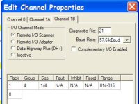
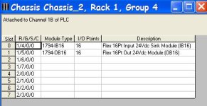
See pictures below on setting up channel 1B and the flex I/O chassis with modules. You need to setup the channel, chassis setup is optional but makes for nice documentation.

See switch setting below
S1 S2
1-on 1-on
2-on 2-on
3-on 3-on
4-on 4-on
5-on 5-on
6-off 6-on
7-off 7-off
8-on 8-on
See pictures below on setting up channel 1B and the flex I/O chassis with modules. You need to setup the channel, chassis setup is optional but makes for nice documentation.


Mickey
Lifetime Supporting Member
Mickey
Lifetime Supporting Member
Block Transfers are not needed for discrete modules.
Have tried the above options and no luck. When i try the 'Edit Channel Properties' it says 'Configuration edits not accepted by plc...'. And when i try to put a figure in S:16 it says 'Unable to create data table'. The problems may stem back to the fact I don't seem to have communication between the devices. No light comes on on the PLC-5 or the flex-IO chassis to say they are communicating. Have tried different cables and using a 82ohm & 150 ohm resistor and no resistor to no avail. Help!
sthompson
Lifetime Supporting Member + Moderator
Have tried the above options and no luck. When i try the 'Edit Channel Properties' it says 'Configuration edits not accepted by plc...'. And when i try to put a figure in S:16 it says 'Unable to create data table'. The problems may stem back to the fact I don't seem to have communication between the devices. No light comes on on the PLC-5 or the flex-IO chassis to say they are communicating. Have tried different cables and using a 82ohm & 150 ohm resistor and no resistor to no avail. Help!
You can not make these changes in Run Mode, the PLC must be in Program Mode. In some cases, they must be made Offline and Downloaded to the PLC. Anything that creates new Data Tables you must do Offline and Download.
The easiest way to get the RIO is after everything is hooked up, go into Program Mode, open the Channel Configuration, and have the PLC perform an Auto Config. I can't give you step by step instructions, because I don't have a PLC 5 here that I can do that on, and it has been a long time since I have done one. If you go into Channel configuration, and Click Help, there are instructions there. If it doesn't work, then you need to check your RIO Wiring, and setup. Obviously the Remote Rack must be powered when you do this.
The Blue Hose should have Terminating Resistors at each end. 150 Ohm for 57.6 KB, and 82 Ohm for 115 and 230 KB. These are not optional, they are required. You might get away with a short length of Blue Hose for testing, but they must be on the final Production Installation.
Stu....
Went offline and created a data table in S:16 and configured channel properties and then downloaded. It then came up with ' Apply Port failed: Ext Sts = 0x12. Invalid Parameter in command'. The data table has been created but the channel properties are not configured. Still seem to have no communication between the PLC-5 and the Flex IO chassis. Have blue wire in 1 & clear in 2 with a 150 ohm resistor between the 2 at both ends. Any suggestions?
Ron Beaufort
Lifetime Supporting Member
is this plant still running at all? ...
please don't take this the wrong way – but based on the program file you posted, it looks like you've got a MESS on your hands ...
are your analog modules still working correctly? ...
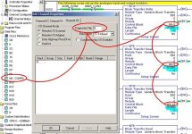
take a look at the figure attached ... apparently you entered the number 9 into the Diagnostic File setting on the Channel Configuration screen and blew your Block Transfers completely out of the water ... notice that all of them are set for a Data File of O:000 and a Length of 0 (highlighted in blue) ... the ZERO length tells the Block Transfer to transfer the maximum amount of words (64) – so that means that your entire four racks of Output table are being messed with ... and notice that all of the Block Transfers are showing Error flags ... if this is the program that you're running right now, it sure doesn't look good ...
I'm guessing that the file N9 was originally used for the control blocks for your Block Transfer instructions ... also guessing: by mistakenly reusing that N9 file, you overwrote all of the configuration data for the Block Transfer Reads and Writes ... oops! ...
suggestion: see if you have a previous copy of your program where the Block Transfers are still set up correctly ... download that and try to get back to where everything was working OK – before you started changing things around for the Remote I/O you've been trying to add ....
if you can get things working again, THEN – and ONLY THEN – proceed to the next post ...
IF (that's a REALLY BIG IF) your plant is still running (analogs and all) then post and say so ... and then please post a copy of the program file that you're currently running ... if the one that you posted before is the current edition, then I don't see how in the world the analog modules could be working correctly ...

Last edited:
Ron Beaufort
Lifetime Supporting Member
now then – IF (that's a BIG IF) everything in the previous post has been taken care of – you SHOULD be able to pick up with the following information and get things back on track ...
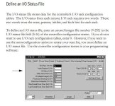
you'll need to be in the Program Mode to create the file ... make sure that you enter a file number that is not already being used ... 11 would be an acceptable number based on the existing program file that you posted ...
this might clear up once you've correctly entered the IO Status File in location S:16 ...
note that you should be plugging the "blue hose" cable from the Remote I/O unit into the right-hand port at the bottom of the processor ... this will be Channel 1B ...
be very careful when setting the DIP switches on the 1794-ASB adapter ... if I remember correctly there were certain series of those that had the switches numbered upside-down ... DOUBLE-CHECK that the switch settings that Mickey gave you are indeed being used ...
also ... you say you are using a 1794-ASB ... is that a /A - or a /B - or a /C - or a /D - or a /E series unit? ... sometimes it makes a difference ... please be specific when you post problems like this ... we need ALL of the information to help you with the details ...
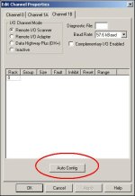
once you get the IO Status File correctly entered, you should be able to use the Auto Config button (shown below) to help you set up the Remote I/O link ... try it ... if it doesn't work, swap the blue and the clear conductors at ONE end of the cable and then try it again ...
the settings that I've shown below SHOULD be OK for the system that you're trying to install ... EXCEPT that I've left the "spreadsheet" part empty ... the Auto Config feature should fill that out for you ...
see if this gets you going ... if not, do you have any other Remote I/O hardware around that you could use temporarily to make sure that the channel is OK - and that the ASB module is also OK? ...
And when i try to put a figure in S:16 it says 'Unable to create data table'.
you'll need to be in the Program Mode to create the file ... make sure that you enter a file number that is not already being used ... 11 would be an acceptable number based on the existing program file that you posted ...
When i try the 'Edit Channel Properties' it says 'Configuration edits not accepted by plc...'
this might clear up once you've correctly entered the IO Status File in location S:16 ...
note that you should be plugging the "blue hose" cable from the Remote I/O unit into the right-hand port at the bottom of the processor ... this will be Channel 1B ...
be very careful when setting the DIP switches on the 1794-ASB adapter ... if I remember correctly there were certain series of those that had the switches numbered upside-down ... DOUBLE-CHECK that the switch settings that Mickey gave you are indeed being used ...
also ... you say you are using a 1794-ASB ... is that a /A - or a /B - or a /C - or a /D - or a /E series unit? ... sometimes it makes a difference ... please be specific when you post problems like this ... we need ALL of the information to help you with the details ...
once you get the IO Status File correctly entered, you should be able to use the Auto Config button (shown below) to help you set up the Remote I/O link ... try it ... if it doesn't work, swap the blue and the clear conductors at ONE end of the cable and then try it again ...
the settings that I've shown below SHOULD be OK for the system that you're trying to install ... EXCEPT that I've left the "spreadsheet" part empty ... the Auto Config feature should fill that out for you ...
see if this gets you going ... if not, do you have any other Remote I/O hardware around that you could use temporarily to make sure that the channel is OK - and that the ASB module is also OK? ...

Last edited:
whew thanks for that Ron. The plant is shut down at the moment so I didn't notice. Have loaded the original program back onto the processor. I have followed all the steps you have outlined above and still no joy. The dip switches are all correct, S:16 is set for 11, the 'blue hose' is in the correct slot, and I tried to auto configure in Prog mode and it comes up with 'AutoConfigure completed successfully but remote I/O rack(s) possibly overlap local I/O rack(s)'. Nothing came up in the 'spreadsheet' and still didn't seem to be communicating so swapped the blue and clear wires around at 1 end and auto configured and it came up with 'AutoConfigure not successful - make sure I/O status file exists'. We do have other RIO hardware on plant so will try them to check the channel and ASB module, tomorrow. The ASB module is series E
Similar Topics
I am trying to send some datas from PLC-5 to control logix plc through 1756-DHRIO. When I go online to PLC-5, Message instruction gives error &...
- Replies
- 15
- Views
- 3,372
My PLC is a TRIO Flex 6 Nano and my HMI is a LT4301 Proface. I have a sensor wired up to the hmi and its working correctly. I want to have the HMI...
- Replies
- 12
- Views
- 3,588
My customer has a PLC-5/80 with 20+ RIO racks. They've asked me to remove one of the racks without shutting the system down. Can I set the...
- Replies
- 15
- Views
- 3,992
Hi,
I am trying to learn how to use my encoder with my PLC. I recently got a high-speed counter module (H0-CTRIO2) for my DirectLogic05 PLC. I...
- Replies
- 5
- Views
- 2,213
I have been doing some research on data highway and data highway plus, and have contacted Allen Bradley for information regarding communication...
- Replies
- 10
- Views
- 2,850


