ControlLogix with RemoteIO

Join Date
Nov 2010
Location
Pennsylvania
Posts
5
I am looking for a quick tutorial on how to use AB RemoteIO with the ControlLogix processor. I have the card in and the network configured per AB documents and it somewhat works; I can read inputs but the outputs won't set. Also what is the correct way to map these I/O into your tags to be used by the Ladder?
 
Its AB FlexIO connected via 1794-ASB

Well, that is more information, but still pretty sparse. What Digital Input/Output and Analog Input/Output Modules are on the ASB? Which Modules are working and which ones are not? Is it an entire Module, or just certain Points? What RIO Speed are you using, do you have the correct Blue Hose Cable and Terminating Resistors installed?

If you could answe these questions, it would be a big help. The best thing would be to post your Program File (Zip it First) so we can see the setup.

Stu....
 
and please don't be offended, but make sure the processor is in the Run mode ...

(yes, sometimes it's something quite simple) ...
 
OK, off hand I don't have the module types but they are all digital, no analog; It happens on every module I checked, didn't check them all as there are about 70. I was trying to force and I had the PLC in all modes; no offense taken, thanks! But really, how should I be moving the bits to the I/O blocks from the tags used in the ladder?
 
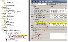
we won't be able to nail everything down in detail without your program and a complete I/O module list - but maybe the following "down-and-dirty" example will point you in the right direction ...

basic idea: toggle those highlighted bits ON - and the outputs should turn ON ...

potential "gotcha" ... on some of the remote I/O module types, the LEDs won't light up unless I/O power is applied to the module ... so if you have the I/O power off (as for "safety" reasons while commissioning) then you might not have a problem at all ... maybe the outputs are coming ON - but the LEDs might not be lighting up ...

remote_io_clx.JPG
 
Last edited:
Ron, Thanks; this is helping as it confirms I am on the right path. I have configuration very similar to above (I would have attached a picture but haven't figured that bit out yet). I have drilled down to the bits you indicated toggling them with and without force in effect and all modes of PLC. The inputs work but the outputs don't seem to; you make a good point about the power but I think it is on (I can't be 100% sure as I am working remotely, through other eyes, the facility is have way across the country). But in any case you think if I force those bits the outputs should go. . i.e. if my configuration looks like yours there is nothing else required to make the outputs go? I will get further time to test later today and do more to confirm the power situation.
 
Ron, Thanks; this is helping as it confirms I am on the right path. I have configuration very similar to above (I would have attached a picture but haven't figured that bit out yet). I have drilled down to the bits you indicated toggling them with and without force in effect and all modes of PLC. The inputs work but the outputs don't seem to; you make a good point about the power but I think it is on (I can't be 100% sure as I am working remotely, through other eyes, the facility is have way across the country). But in any case you think if I force those bits the outputs should go. . i.e. if my configuration looks like yours there is nothing else required to make the outputs go? I will get further time to test later today and do more to confirm the power situation.

This may seem obvious, but just in case, did they Enable I/O Forcing while they were testing the Inputs/Outputs?

Stu......
 
Just to close the loop on this; everything now seems to be functioning as expected. The one difference is instead of examining the LED's on the I/O panel, we just started the system so there must been some power disconnect as suggested. Thanks again!
 

Similar Topics

Why does the controllogix redundancy modules use a single mode fiber vs multimode fiber?
Replies
1
Views
80
Hello, I have two 16 point input cards and 1 16 point output card showing module faulted on my IO tree in Logix Designer. The fault code is...
Replies
7
Views
214
Hello, My associate and I are trying to sync up two ControlLogix racks (7-slot chassis) with identical modules. We are able to see the secondary...
Replies
4
Views
194
Trying to setup a message read via Ethernet. I have the path setup as 1, 1, 2, 192.168.66.10 I get an error code 1, ext err 315. I am beating...
Replies
9
Views
231
I have a redundant ControlLogix being set up. This program reads a value from a remote site which happens to be SLC PLC. Rockwell mentions SLC...
Replies
2
Views
96
Back
Top Bottom