Question about setting bits! (Picture)

Fropitar

Member
Join Date
May 2011
Location
So Cal
Posts
24
Hello all, hope everyone is having a good weekend.

I'm a novice to PLC's programming, trying to learn on the fly to further my skills and career. I'm hoping someone could help me out with a bit question I have.

I'm using a Eaton ELC PLC, and I have an input card for Thermocouple.

The Instruction sheet for the Card has the instructions, I just may need a bit of help translating.

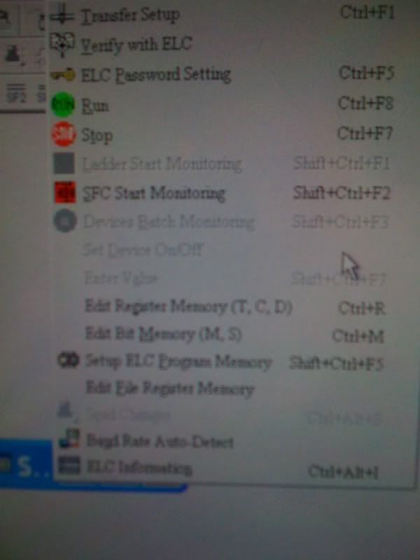
The Software i'm using is ELCSoft.

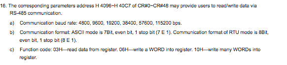
Here is the picture of the instruction sheet:

CR.jpg


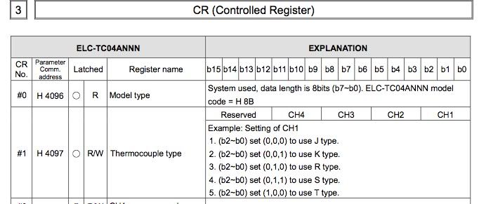
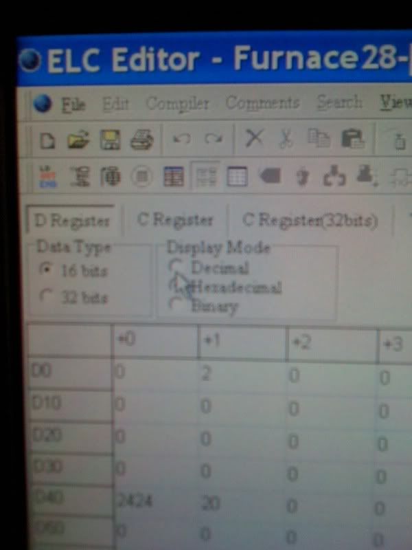
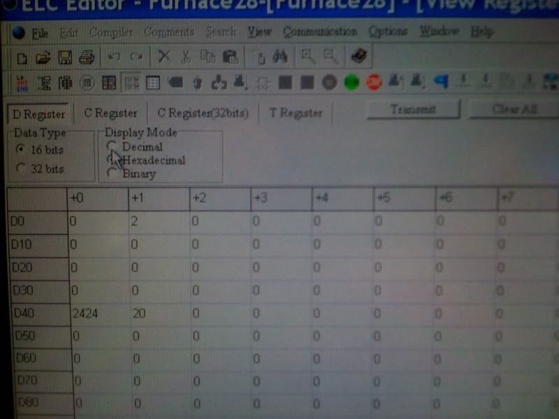
I've already set Registers in the PLC to hold values, but never on the "b2-b0" level like in the picture

I've used:

the command "TO K0 K19 D20 K1"

Which Writes from K0(My module/card) the Control register K19's value (My thermocouple reading on channel 1 of the card) to D20 (Register 20) writing 1 word at a time (K1)

However, I'm lost when it comes to the example on the picture.

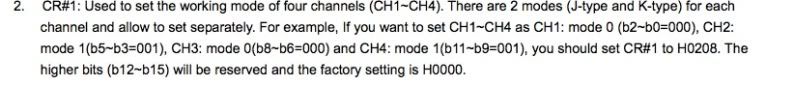
I know I need to set Control Register #1 to my Thermocouple type (Type K). The example states "2. (b2-b0) set(0,0,1) to use K type"

I'm unsure how to set bit 2-0 to 001 (I assume thats what they mean)

Does anyone remotely understand what i'm getting at? Do I need to provide more info?

Edit: PDF to the Module instruction sheet http://www.alliedelec.com/Images/Products/Datasheets/BM/EATON_CUTLER_HAMMER/416-0396.PDF
 
Last edited:
Welcome, and great first post.

It seams like H4097 needs to be set to 001

(caution, I have not used this PLC)

Good luck
 
DISCLAIMER: I've never worked with your brand of PLC - but if you were working with an Allen-Bradley, we'd tell you to go to the appropriate bits/boxes (right on the data table) and type ONEs and ZEROs into the bits/boxes ...

specifically, when you're configuring a module (which is what it APPEARS that you're trying to do, then you NORMALLY don't use ladder logic commands to control the status of the bits ... basically, you USUALLY just manually set the ONE and ZERO patterns in the appropriate bits/boxes - and then move on ...

EXCEPTIONS: in some VERY RARE cases it becomes necessary to change the configuration of a module "on the fly" ... in those cases, you might have to write ladder logic controls to manipulate the bit patterns ... I doubt that's something you need to worry about at this stage of the game ...

hope this helps ... welcome to the forum ...
 
Here is another Blurp from the instruction sheet.

This is the Controlled Register I need to write to, im not sure how this adds up and makes sense though.

cr1.jpg


I dont see the relations between setting the bits, and the outcome. How do the setting of those bits equal "H0208" in that example?


I feel like this: ;)
 
1. Ignore the "B2-B0" stuff. They made it harder than it has to be.

2. Type "K" is "1', remember that.

3. Open your Windows calculator, make sure that you are in the scientific mode.

4. Set the type to "Oct"

5. Assuming you want all 4 channels and that they will all be "K' type enter four ones (1111)

6. Select "Dec" mode and see 585. This is the number you will enter into "H 4097"

7. To summerise the type (0=J, 1=K, 2=R, 3=S, 4=T) is entered for the four positions. The rightmost is Channel 1. Do this in octal then press decimal.


Edit - They are stressing entering values in Hex. OK we'll do that.

For their example in octal mode enter "1010" then press Hex. You'll see the "208". In the example I gave (all 'J' type) we again enter the "1111" while in octal but this time press Hex. You'll see "249" which would be entered (I guess) as "H 249".
 
Last edited:
I bet H0208 is hex value size of 16bits. As bin (bits) it would be 1000001000 and few leading zeroes.
 
Last edited:
1. Ignore the "B2-B0" stuff. They made it harder than it has to be.

2. Type "K" is "1', remember that.

3. Open your Windows calculator, make sure that you are in the scientific mode.

4. Set the type to "Oct"

5. Assuming you want all 4 channels and that they will all be "K' type enter four ones (1111)

6. Select "Dec" mode and see 585. This is the number you will enter into "H 4097"

7. To summerise the type (0=J, 1=K, 2=R, 3=S, 4=T) is entered for the four positions. The rightmost is Channel 1. Do this in octal then press decimal.


Edit - They are stressing entering values in Hex. OK we'll do that.

For their example in octal mode enter "1010" then press Hex. You'll see the "208". In the example I gave (all 'J' type) we again enter the "1111" while in octal but this time press Hex. You'll see "249" which would be entered (I guess) as "H 249".


This helps. I believe the H4097 is for RS485 comms though.

cr3.png
 
DISCLAIMER: I've never worked with your brand of PLC - but if you were working with an Allen-Bradley, we'd tell you to go to the appropriate bits/boxes (right on the data table) and type ONEs and ZEROs into the bits/boxes ...

specifically, when you're configuring a module (which is what it APPEARS that you're trying to do, then you NORMALLY don't use ladder logic commands to control the status of the bits ... basically, you USUALLY just manually set the ONE and ZERO patterns in the appropriate bits/boxes - and then move on ...

EXCEPTIONS: in some VERY RARE cases it becomes necessary to change the configuration of a module "on the fly" ... in those cases, you might have to write ladder logic controls to manipulate the bit patterns ... I doubt that's something you need to worry about at this stage of the game ...

hope this helps ... welcome to the forum ...


You're right, I'm trying to configure a module. You also sound correct when you say i should be setting this manually and NOT using ladder logic. I won't be changing on the fly. Right now I wish my boss wasn't so cheap and would have bought the SLC500. haha.


I assume you mean one of these tables:

ba38b87b.jpg


Here is two pics of the Register Memory table:
3700d039.jpg


30e3dcd5.jpg


Not sure how to tell which register is the proper one for the module, and module register I need set. =\
 
Alright gentlemen! I want to thank you all for the help.

As repayment, I offer you a good laugh at my own expense.

After taking all the information in and making adjustments, I've spent the last two hours scratching my head as to why my Thermocouple probe is reading out at 806-815. I was so dead set on the Thermocouple type still being set wrong.

It turns out I just had the decimal set wrong on my HMI Screen. It was reading 80.6, and 81.5 the whole time, which is the ambient temp! I got caught thinking too hard.


Thank you ALL for the help!

I couldn't have set the module for the correct TC type without you.

I hope you all are enjoying your weekend instead of putting in free hours of labor like myself.

So how did you do it? Maybe someone else needs the information.
 
So how did you do it? Maybe someone else needs the information.

View->Edit Register Memory->Click "D" Register memory.

I set register D11 for H0249 via the above mentioned menu.

I had to set the module bits for thermocouple type via ladder logic. (Even the factory guy didn't know how to manually set the module via ELCSoft menus)

To send register D11 into the module "Controlled register #1" (Thermocouple type) I did the following in the ladder logic:

"LD M1002" Which is a N.O. Contact that makes on the first scan of startup, followed by "TO K0 K1 D11 K1"

Command: TO
Module: K0
Controlled register 1: K1
Register to send: D11
Words to send: K1

-----||----------------------------[TO K0 K1 D11 K1]
M1002

Thanks again to all, especially for the help understanding bits, and the hexidecimal/Octal a bit more.

Hopefully one day I can help contribute.
🍺🍺


-Brad
:site:
 

Similar Topics

hi , I need to sorry for my bad English first. I'm newbie at plc programming ,I had been asked about E/IP protocol information for some system...
Replies
3
Views
379
I understand how to connect to the HMI, and Send the current Time and date from the Laptop to the HMI using Crimson 3.0 When I power down the...
Replies
3
Views
3,584
Need some clarification regarding the devicenet set up PLC is CLX with 1756-DNB scanner, trunkline using kwiklink flat cable with the micro...
Replies
7
Views
5,146
The PLC for this application has DINT tags ALARMS[0], ALARMS[1], ALARMS[2] etc. Within each of those are individual alarm bits ALARMS[0].0...
Replies
11
Views
6,104
On this link - http://domino.automation.rockwell.com/applications/kb/RAKB.nsf/0/F136DED23C7F35CD85256AFB00620F9E?OpenDocument What does jumper...
Replies
0
Views
1,435
Back
Top Bottom