Micrologix 1100 wiring with a relay

rbautomacao

Member
Join Date
Jul 2011
Location
Brasil
Posts
19
Catalog number plc: 1763-L16BBB

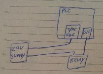
Im confusing about wiring a relay with the plc ..

I dont know if i use this option ..

option1.jpg

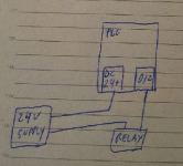
Or this one:

option2.png

The plc has too a Dc24- output port ? When i use it ?

Thanks for any help...
 
The +24 and DC COM and GND terminals are on the bottom left side of the controller. These are to provide the actual power to the controller.

Your first diagram is correct for the wiring of a DC Output to a Relay.

The CPU power and the Output power are not internally connected so that the Output power can be controlled by an Emergency Stop and separate fusing from the CPU power.
 
Your second diagram is also correct. You can use outputs O/2 to O/5 only with 24VDC relays, valves, motor starters etc. You can not use AC.
 
For the best understanding, please read and understand the User Manual, publication 1763-UM001, available from literature.rockwellautomation.com.

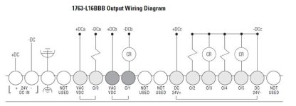
The first two Outputs on a 1763-L16BBB controller are relay contacts; you can use any source voltage.

Outputs O/2 through O/5 are Solid-State outputs with a single "DC 24V +" voltage source pin. This voltage source is not provided by the Controller power input terminal.

1763L16BBB Output Wiring Diagram.jpg
 
Last edited:
Your second diagram is also correct. You can use outputs O/2 to O/5 only with 24VDC relays, valves, motor starters etc. You can not use AC.

In a previous thread the OP said he had a 1763-L16BBB.

No the second drawing is NOT correct. Reread Ken's post. See drawing below.

Edit: Ken types faster then I do.

ControllerPower.jpg
 
I think the second drawing is *almost* correct. It lacks the connection of the DC- terminal for the DC solid-state output group (O/2 through O/5).

I overlooked the fact that he properly labeled the different voltage source terminals for the Relays "VAC VDC", and the DC Solid State outputs "DC 24+" in each drawing, even though they are in the same place in the drawing.

The User Manual diagram is the authority here.
 
Ken,

What is the wattage for the FET sourcing outputs. Could you point me to where this info could be found. I am planning to connect a RED HAT Solenoid Valve Coil, 24VDC, 11.6W to the FET so that I do not have to power it separately.

Also, if i am using the relay output O:0/0, whats the max amp rating through these output relays.

Are O:0/4 and O:0/5 the fast FET. whats the difference between fast and the (O:0/2 or O:0/3).

Thanks
Karthik
 
It would be ideal to create a new thread; this one is a few years old and may not refer to the specific controller you are using.

All of the information you seek is in the MicroLogix 1100 User Manual, publication 1763-UM001.

It is available from the RA Literature download server.

In general, a small 12 watt valve is going to pull less than half an ampere, so it's well within the per-point limit of those solid-state outputs. They can provide 750 mA all the way out to their thermal limit at 65 C.

The relay outputs on MicroLogix 1100 controllers are 5A relays. There are lifetime and common grouping ratings in the User Manual.

Remember that these outputs are powered by whatever you connect to the DC source terminal, not by the controllers internal power supply. Running a solenoid off the "Auxiliary DC Supply" on the AC-powered MicroLogix is asking for trouble.

The 'fast' outputs are able to be used by the fast output hardware functions (PWM and PTO). When they are used as general-purpose outputs they have the same ratings as the other solid-state outputs. When used with the high-speed functions, they are significantly de-rated (to about 100 mA).
 
If I'm following up on answers to my old threads from years ago.... I'm spending too much time here.

I'm off to Osaka for a week. Cheers !
 

Similar Topics

I have a MicroLogix 1100 and it's capable of ac or dc output voltages. What I don't know is how I'm supposed to tell the 1100 to use dc for the...
Replies
13
Views
1,406
Hello, After searching the web a bit, I am still not quite sure how I should go about wiring up this controller. It is mostly built for 120V AC...
Replies
5
Views
2,039
How can i connect/wiring auma actuator to ml1100 (1763-l16bwa) for open, close and stop.
Replies
4
Views
1,838
Hi, I cannot find the DLCA1764.EXE utilty software for data retrieving. Can someone share the link to download this software. Thanks!
Replies
4
Views
121
I am currently backing a Micro Logix 1100 and no-one seems to have the file for me to upload from. Is there a way for me to upload the project off...
Replies
15
Views
520
Back
Top Bottom