PLC MicroLogix 1100 wiring

palmersc

Member
Join Date
Aug 2020
Location
IA
Posts
6
Hello,


After searching the web a bit, I am still not quite sure how I should go about wiring up this controller. It is mostly built for 120V AC inputs and outputs.


I am at my home playing around with this thing and looking to put a few switches in and a few devices to power per the program logic.


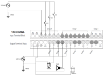
Attached is a schematic I drew in Visio---my attempt to remember from school some of how electrical diagrams work.


I am wondering if you could take a look at the way I am routing the power from the supplies to switches / components. Am I understanding the way these controllers handle power? I'm more sure of the switches on the input side than how I go about wiring the output.


Thought I would post something here quick before I go about wiring this up with real energy.


Thank you!


P.S. would 14 guage romex wire be about right to handle anything you would put on a 15A circuit in the home? Any wire type suggestions are welcome.
Annotation 2020-08-21 104503.png
 
Looks good to me but you may need a interposing relay on the motor depending on the size of it
 
A simple start could be just connecting hot, neutral, ground to an old power cord to get the PLC powered up. You can go online and force or toggle bits to see logic running. When you add the I/O, it might be handy to make a separate power source for that. I suggest the I/O power be fused less than 15A, maybe 5A depending on the output devices. Use a GFCI protected power source. Make sure the motor or anything else doesn’t exceed the rating of the output contacts. Romex sounds awful to me. I would usually use stranded 14 or 16 for something like this.

Have fun and be safe.
 
Cool, thank you.


So I can think about the black hot wire going into the PLC outputs, being continued over the relay per the logic, and remaining the hot black wire until it gets to the load. On the other side of the load I might think of it as the white common wire? I'm likely going to put in outlets at each of the outputs so I might plug in appropriate devices. Will look into what you mention for any motors I consider.


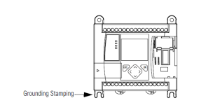
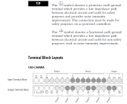
As far as grounding goes, can I ground the tab on the controller and it serve as the ground for the entire system? Does the protective earth ground terminal need to be addressed? I've attached a couple screenshots from the manual about this.

Annotation 2020-08-21 110524.png Annotation 2020-08-21 110609.png
 
Yes, the AWA is a AC power AC inputs and Relay outputs so just like you did the hot wire will be on the common and it will switch as the logic does in the PLC and the neutral will be always connected to the neutral side of the load

For the ground the terminal should be enough, the ground on the tab is so its grounded when mounted in a panel... you can check it with a ohm meter and see but they may be tied together in the PLC
 

Similar Topics

Hello everyone I have a problem of losing the ip address of the micrologix 1100 and 1400 PLC each time I lose power. the problem is that I...
Replies
0
Views
1,781
Hi All, Hopefully someone can give me an answer on this one. I need to communicate to a Micrologix PLC from Wonderware. Do you know if the...
Replies
4
Views
4,143
Greetings, (My first post) I have a MicroLogix 1100 Processor. I have downloaded RSLinx Classic. I have also downloaded RSLogix micro English...
Replies
24
Views
8,950
Hello all, I have a MicroLogix 1100 Series B that I am trying to read data from and into a PLC-5/20 Series D Rev A. I assume this is...
Replies
1
Views
3,699
Hey friends, Need to generate analog signals in MicroLogix 1100. Please help with how to configure the I/O devices. It would be very nice if...
Replies
4
Views
2,027
Back
Top Bottom