Please share some guidance : Installing VFD on PIMMs

jiro.iro

Member
Join Date
Jul 2011
Location
Surabaya
Posts
8
Hi,
This is not PLC-related. Hope it's ok to post here.:unsure: I've searched the forum but didn't find an answer.

I work with several fully-hydraulic PIMMs (plastic injection molding machines). In a few months we plan to add a VSD to each machine with the purpose of electricity saving. The motors are 3-phase 380VAC induction motor. Unfortunately, not many people around us can provide informative answer. So we'd really appreciate your expert advice.🤞🏻

Some of the questions are :
1. Do we need to add a feedback encoder card to the VFD? If we don't, how does the VSD know when to change the frequency?
2. Do we need to add braking to the VFD in PIMM application?
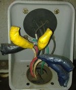
3. How do we measure maximum load amps of the motor when used? There are six terminals on the motor cabinet, namely U1, V1, W1, U2, V2, W2. See picture attached.

Thanks a lot, guys!(y)

15072011831.jpg
 
Hello, and welcome to the forum. VFD questions are welcome here, and there are many experts in the field. In my non-expert but experienced opinion:

1) No. Modern drives can be used which have quite accurate methods of determining motor position, which unless you need postiion control (I know little of injection molding). Even volts per hertz 3 phase VFDs can do a pretty good job in the upper 60% of rated motor rpm, of controlling speed in reaction to pressure commands. If you need for the motor to "sit still" at full torque, then yes, I would recommend encoder feedback, or if you need precision information about the position of the driven equipment, then Do use encoder feedback to the drive.

2) Dynamic braking is called for when the driven equipment is an "overhauling load"...think slowing down a train, by applying a decreasing frequency and then the VFD leterally absorbs that motor-turned-generator right back onto the DC bus. So if you are launching big heavy objects and then decelerating really hard, the DC voltage applied to the bus will exceed its capacity, it will (hopefully) Fault! and "Let Go" of the load which will freewheel (sometimes, right off the end of the tracks).

If the ratio of the motors rotor to its load is too low, and it needs to frequently decelrate "into an overhauling load", then you need to add them. Plan for dynamic braking when in doubt as far as panel layouts, then you can return them un installed if your measurement of the VFD DC bus terminals does not show a problem during deceleration, when the motor becomes a generator.

3)The motor is wired Delta http://www.google.com/imgres?imgurl...&ndsp=44&ved=1t:429,r:3,s:0&biw=1463&bih=1044

The VFD will likely be fine with that, but the specifications of the motor may make it sensible to rewire it in WYE configuration. Check the motor data plate or spec sheet.

Please wait for drives an injection molding expert to correct or confirm my guesswork before taking action!

Paul
 
Last edited:
Hi Paul,
Thanks for your kind reply.:D

My own understanding of how a PIMM works would be a motorized pump is supplying hydraulic oil all over with a constant rate while it is up to the many valves to open and/or close to supply and/or stop the pressure and flow to/from where the "action" is. In the many stages in one cycle, there are different motor speeds required. We do not require motor speed at the maximum at all time. There is sometimes a cooling stage when we practically don't need any oil supply (but the stage is very short and often skipped). To PIMM experts, please don't hesitate to correct me.:oops:

Now, I have a question myself, does the speed of motor will affect the pressure or the flow or both?

About maximum amp load draw, I'd like to know how to measure using a clamp meter. I want to know during one cycle, what is the maximum amp draw. I need an advice as to which wires to measure, is it one by one or altogether?

Thanks a lot, guys!
 
Last edited:
Dude,
you are playing a serious game. I don't have engineering experience with plastic injection molding, but I operated a few before I got a degree and went into controls. My understanding is that they have precise timing cycles and every cycle must be exactly the same as the last. If they are not, then bad parts start coming out.


Do you work for an OEM ? or have you bought this machine as a customer ? if you bought it, putting a VSD in is certainly going to void any warranty and make the machine harder to repair when it fails (maybe not a lot harder- depends on how smart your maintenance guys are =)


A few years ago, I interviewed for a job at a large PIMM machine maker. Their latest machine included a very large servo motor (for precise positioning) in place of the hydraulics- it seems that the hydraulics did not have the process repeatability that they wanted, so they started using (very expensive) servo drives and were doing testing (months) before shipping.

Most hydraulic system's I've seen have an unloading or recirc. valve that reduces motor load when there is no hydraulic demand- your clamp-on ammeter will tell you this (measure one wire at a time). a VSD might save you a bit more money in electrical use, but remember that you are now adding start and stop cycles to the motor, which slowly accelerates its failure. You are also adding cost to the price of the machine and you are adding something else that can break and stop production.

One way to mitigate the additional failure point is to install a 'bypass contactor' that, when closed, removes power from the VSD and puts line voltage directly on the motor - this lets you run the machine even if the VSD is broken. how costly is your machine downtime ? (rhetorical question)

I'd plan on a lot of testing time/parts/material if you are at all concerned about product quality over 1000's of cycles.

I don't think that you'll need braking if you are just running a hydraulic pump.

How does the VFD know when to speed up and slow down ? You'll have to tell it ! either using relays on the PIMM controller or an external PLC/timer that is synchronized to the PIMM controller somehow. does your controller have relay outputs ?


-John Grube
 
To go to the heart of the issue, using a VFD to save energy on a hydraulic power pack on a PIMM is going to be a disappointment. VFD's don't save energy---they simply permit the LOAD to reduce its energy consumption. In order for the load to do that, you almost always must reduce speed. On PIMM's, while it is true that some speed change is possible, unloading the motor with a pressure relief valve accomplishes almost the same energy reduction without a host of other bad things happening.

Without knowing all of your machine details, I would expect that adding a VFD to your machine is a mistake.
 
VFD for Injection Molding Machine - NO

Dude,
you are playing a serious game. I don't have engineering experience with plastic injection molding, but I operated a few before I got a degree and went into controls. My understanding is that they have precise timing cycles and every cycle must be exactly the same as the last. If they are not, then bad parts start coming out.


Do you work for an OEM ? or have you bought this machine as a customer ? if you bought it, putting a VSD in is certainly going to void any warranty and make the machine harder to repair when it fails (maybe not a lot harder- depends on how smart your maintenance guys are =)


A few years ago, I interviewed for a job at a large PIMM machine maker. Their latest machine included a very large servo motor (for precise positioning) in place of the hydraulics- it seems that the hydraulics did not have the process repeatability that they wanted, so they started using (very expensive) servo drives and were doing testing (months) before shipping.

Most hydraulic system's I've seen have an unloading or recirc. valve that reduces motor load when there is no hydraulic demand- your clamp-on ammeter will tell you this (measure one wire at a time). a VSD might save you a bit more money in electrical use, but remember that you are now adding start and stop cycles to the motor, which slowly accelerates its failure. You are also adding cost to the price of the machine and you are adding something else that can break and stop production.

One way to mitigate the additional failure point is to install a 'bypass contactor' that, when closed, removes power from the VSD and puts line voltage directly on the motor - this lets you run the machine even if the VSD is broken. how costly is your machine downtime ? (rhetorical question)

I'd plan on a lot of testing time/parts/material if you are at all concerned about product quality over 1000's of cycles.

I don't think that you'll need braking if you are just running a hydraulic pump.

How does the VFD know when to speed up and slow down ? You'll have to tell it ! either using relays on the PIMM controller or an external PLC/timer that is synchronized to the PIMM controller somehow. does your controller have relay outputs ?


-John Grube


I concur with Mr Grube,
There is a known evolutional history of Injection Molding machines. Primarily Hydraulic origin, very wasteful, you have hundreds of horsepower of motors on line to deliver the short burst of energy during injection, and another steady load during plstication (screw rotate). Then the motors are idle and wasting energy during cooling.

There have been companies selling VFD for energy savings on IMMs, and yes you do save a few cents in electrical use, BUT the VFD can not ramp up fast enough to meet injection speeds.

Molded scrap is costly.

2011 monies spent on 1980's technology is foolish.

Your better investment is in NEW controls with high response injection control algorithms, and NEW 2011 highly responsive hydraulic injection controls valves.

Check out Bosch Rexroth HACD injection/clamp control.

Retrofits are good sense for large tonnage machines, 500 Tons and above.

If it is a small tonnage machine, scrap it, and buy a NEW machine.
 
Hi,
Thanks John, DickDV, Plastic.(y) We've owned the machines for more than 10 years. So they are old PIMMs.

These machines run with many proximity switches. Each stage begins or ends when a switch sends signal. Can these signals be used to "tell" VFD?

It looks like most of you guys do not take installing VFDs as a good move. I'll take a look at retrofitting, changing controls. But any more opinions are welcome.:nodi:

Thanks a lot.
 
I'm surprised Peter hasn't popped in yet, this sort of thing is right up his alley. I think his usual advice in this situation (I personally have zero experience with hydraulics) is to install an accumulator to take care of the sudden surges of power needed and size the motor/pump to handle the average load, not the peak load. With the motor working at near its full capacity for the whole time, you get better efficiency and you get to use a smaller motor.

I'm sure he can describe it much better than I can, you might want to PM him.

Brian
 
I used to work for a compnay that had lots of PIMMs. The best solution I ever saw was a varable pump. These can change volume rates rapidly with in turn ment less oil retuning to the tank "unused". For the most bang for your buck I would look into this before playing with a VFD. The only advantage I could see for using a VFD would be if you had a rather large (in excess of 30 seconds or better) mold open time when you did not need the oil volume. Also you can use accumalators to store up oil during the periods of your cycle when demand is down and then these accumalators can dump the oil apaond demad via a valve. We added accumlators to our process to increase spead without having to increase pump volume.

Also someon mentioned Peter stepping into this. Peter will be able to give you the math on what I just said. I am not that smart, I just know what works.
 
Hi guys,
Thanks to Brian123 and Clay B.:)

I'll consider your feedback. Accumulators could be the answer. However, to add an accumulator and replace to a smaller motor is no less expensive than to add a VFD, is it? But of course if a VFD doesn't bring the saving we expect, we should find other alternatives.

Our cycle is normally less than 15seconds depending on the products and yes, it rarely goes completely silent (cooling stage).

Any other feedback will be appreciated.:)

Thanks.
 
If your looking to slow down the motors that drive pumps and control the vfds with switches then i cant see why this won't work. The decel and accel time on new vfds are astonishing. Why couldn't you program presets into the vfds and control them with external switches.
 
Some of the questions are :
1. Do we need to add a feedback encoder card to the VFD? If we don't, how does the VSD know when to change the frequency?
2. Do we need to add braking to the VFD in PIMM application?
3. How do we measure maximum load amps of the motor when used? There are six terminals on the motor cabinet, namely U1, V1, W1, U2, V2, W2. See picture attached.

1) to have return signal to VFD it depend on what type of VFD you buying or using ..in asia there are bunch of VFD which call encoder attach which 1 of it was AB for sure.

3) for my knoweldge...when you wanna connect to VFD you need to delta the motor terminal..mean only 3 cable.. and you can measure the voltage at VFD terminal on HZ ..coz hardly to get voltage reading at terminal..
 
Do not be tempted to measure anything, yes, that's anything, on the leads between the VFD and the motor.

First, There isn't a piece of test equipment made that will accurately report Hz, effective voltage, and effective current on the complex, high frequency pulses that the VFD sends to the motor.

Second, it is hugely unsafe to contact the motor leads due to the voltage being far higher that expected. For example, in a 460V system, the voltage on the motor leads can be in excess of 1400V. In a 400V system that would be over 1200V. And you are trusting a CAT III 1000V meter!!!!

Third, the frequency, voltage, and current are all available from the display on the drive and it will be accurate too.

Bottom line: don't touch or test the motor leads with anything and that includes current transformers.
 
Would someone please attach a complete hydraulic schematic of this PIMM? Also it would help alot if you posted the vfd/vsd manufacturer.
Dick DV is right about the amps and voltage being available on the display screen under the read only parameters. Seeing how the vfd would idle the pump inbetween cyles ie min speed parameter there would be no start/off cyle or repetitive inrush used. As stated above i don't see where you would need braking controlling the pump.
 
Hi guys,
Thanks to Bubba271, ajay34 for your feedback.:D The complete schematic may be hard to find, but I'll try. We have not decided on which VFD brand to use. We are considering some Japanese brands like Fuji Elec, Yaskawa, and Hitachi.

Thanks to DickDV for your warning.

Iro
 

Similar Topics

please help me . I have to make this ladder diagram and I can’t figure it out :(
Replies
12
Views
182
Hi , Where i can find Mitsubishi PLC Card end of line & replacement model details. i am looking for Q02CPU replacement model. Please advice. thanks
Replies
2
Views
126
Hello, I am trying to get a Yokogawa Hart pressure Transmitter and a Rosemount Temp Transmitter to read on a 1769-IF4 module on an L33ERM...
Replies
10
Views
377
Please help me, I have solve many week but still not solve it. I found trouble of factory talk studio when I set tag by browse address of OPC...
Replies
0
Views
118
Back
Top Bottom