Siemens S7300 FB41 PID help

tom_ocean

Member
Join Date
Jul 2011
Location
florida
Posts
6
Hello all,
I am an electrical engineering student working on a senior design project with an industry sponsor. We are automating a burst test chamber and are completely new to plc programming. We are using siemens step 7. Trying to use a pid control function to ramp the pressure up inside a hydraulic hose following an exponential or linear setpoint curve. I am having trouble figuring out exactly how to configure this fb41 correctly for a changing setpoint. I have a basic understanding of all the different parameter of the function block, just don't know how to use them correctly apparently. Any help would be awesome. Thanks
 
Where are you calling FB41? If you don't call it out of OB35 (or other timer OB, depending on CPU) with the interupt time set to the same value as the "CYCLE" parameter in FB41 you'll get weird results and won't be able to get the control properly tuned.
 
I first created it in ob1 then read it needed to be called in ob35. I moved it to ob35 and created the db instance through start>simatic>step7>pid control paramter assignment. I made PVPER_ON true, using the P_sel and the I_sel, set the cycle time equal to the ob35 time, PV_PER is coming in from a "mw" assignment in ob1 moved from a "piw" assignment. I am assigning SP_int from a "md" memory I am writing to in ob1. The set point is changing every second in ob1. When I transfer the program to the PLC the SF red led comes on and I don't get any output. I can't figure out from all my reading what is going wrong. Any help would be awesome thanks
 
Hi!
You can get diagnosis if you highlight the CPU icon, rightclick, PLC / Module Information.
If you cannot understand it, post it here.

But I could always guess; you've forgotten to download the FB41 or it's instance DB, or you're addressing a non-existant analog in/out.

Kalle
 
Any help would be awesome thanks

Using Simatic manager create a new library called PIDLib (File>New then click on the library tab). Insert an S7 program into the library and then copy your blocks from your project to the library. Archive the library and then post the zip on here as an attachment. (The project will very quickly exceed the size limit for posting as an attachment - that is why you need to create a library to post).
 
Here is the archived library. The comments in ob1 are no good, I've just been copying and pasting blocks trying different things, so I haven't kept comments current. Like I said, I am completely new at this stuff, this is my first PLC project with no formal PLC training, so I don't even know that I am attempting to set this PID up correctly for what I'm trying to do. I need an incrementing setpoint, looking for an exponential or linear pressure curve, that increments up to a "max psi" input by the user within the "time" the user inputs. Thanks for your help
 
I agree with Kalle. Make sure you check that you have downloaded FB41 and all the other blocks in your project. It's very easy to call an FB (which creates the FB in your project but does not download it to the PLC). This can cause the PLC to go into stop mode.

You could try putting in OB121 which may keep the PLC in run mode while you work through to diagnosing the fault.

;-)
 
OB121 and OB122 are already in the project. I would remove them at first as you need to find problems and fix them before proceeding further. Make sure you delete them from the plc and the project.

The diagnostic buffer and/or stacks will lead you to your problems.
 
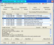
You get the diagnostic buffer from module information - select the blocks folder then press Cntrl+D and select the tab. Here's an example using your code - I do not have the PIW/PQW addresses in my h/w/ config so the buffer shows the bad I/O access:

d1.JPG
 
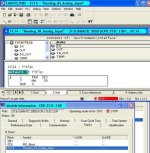
If you click on the stacks tab, you will see the call up path to the point in the program where the error occurred. Click on open block and this will open the block online at the point of the error. In my example the block is opened in STL so the cursor is postioned at the errant line of code. If viewing in ladder, you will get the errant network.

d2.jpg
 
I got the PID downloaded without any errors. I now have a new problem. My output of the PID "LMN_PER" and "LMN" are staying high at 27648. I have played with the gain and the "I" but still get no change in output. While monitoring the instance data block I can see the calculation "LMN_P" changing but the "LMN_I" just stays constant. Also, what is the best way to achieve an exponential increase in pressure, to increment the set point value exponentially or set the gain and deadband time accordingly. My only thought about that is that the user inputs a "time" to max pressure and a "Max PSI" to reach, I think these values would change what the gain and deadband would have to be every time a new test was done with different parameters, seems easier to just use those parameters to calculate an incremental set point.
 
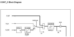
In the code you posted, your are feeding MW39 into PV_PER but PVPER_ON is set to zero, thus ignoring PV_PER - see block diagram.

What did you have to do to fix your previous error ?

bbp.JPG
 
It was a bad output address in my code. I re-wrote my code a little when I ran into my new problem I posted previously but after troubleshooting for a while yesterday evening I finally figured out that my scaling was also bad on my process variable and setpoint causing a huge difference between the two so when multiplied by the proportional gain the output was maxed out trying to get the "PV" up to the setpoint. So I now have the scales all the same and seem to be getting response from the controller I guess now it's just a matter of tuning it. Still I have the question of the best approach to getting an exponential increase in pressure out of it, whether I should increase the setpoint exponentially or keep it fixed and tune the gains and deadband. Tuning the gains and deadband seems to be too complicated to my particular project due to the fact the user has the ability to input different maximum pressures and times to pressure. Thanks for all your help so far it is much appreciated.
 
It seems like if I set ob35 to be called every 100ms and I am only increasing the setpoint every second that ten samples should be enough to be able to tune it to keep up with the set point without many oscillations around it or am I thinking about it incorrectly?
 
Still I have the question of the best approach to getting an exponential increase in pressure out of it

Your setpoint generation must be of the form you require, so if your test requires a variable exponential function, that is what you must code.

What does the analogue voltage feed to produce the hydraulic pressure - a proportional valve ?

Can you relate the actual pressure to the setpoint to provide a feedforward term. If linear then use an eqution or if not then use a lookup table to generate the feedforward term.

Run the system in feedforwards only, then add P and adjust for stability, then add I to reduce the steady state error.
 

Similar Topics

Hi to all, Our company does not usually use Siemens PLCs, but have a press with one in it. We are trying to change the IP address in our Simatic...
Replies
2
Views
1,066
First off, thanks for the patience with my post. Rookie to Siemens. I am trying to use a Retentive timer and it has to be around 24hours. Thus...
Replies
2
Views
1,883
Hi, Is there a simple way to do the following: I have an input from an RTU which is a Real value. The word order from the RTU is different to...
Replies
1
Views
1,166
Hi, I encounter a problem trying to get online to a CPU315, This CPU is part of a MPI network with multiple CPU including a CPU414, When I do...
Replies
2
Views
1,487
We are currently using a number of Rotork IQ valves on a project. The client has a requirement to send/ receive acyclic data from the PLC. This...
Replies
0
Views
1,839
Back
Top Bottom