Slc 5/03 rio scanner

RasPLC01

Member
Join Date
Sep 2011
Location
AUS
Posts
56
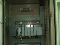
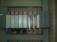
I have a SLC 5/03 PLC which is already installed 5 yrs ago.now im trying to add 1 input and output module to the exisitng one
PROCESSOR is connected to RIO scanner. i would like to add my new cards to adapter side.

when i tryed to configure these cards 1746-im16 and 1746-om16
through software it is showing a message window as

identical cards dectected do you want keep same settings
yes/no

if i press yes it is not configuring correctly
if i press NO iam loosing whole existing programs


Any one can help me please?


settings

PLESE FIND ATTACHMENT
THE NEW INPUT/OUTPUT ARE SHOWN BY DOOR OPENED
SETTINGS.jpg CPU SIDE.JPG ADPTER SIDE.JPG
 
Welcome to the Forum ! Thank you for posting those details about the configuration.

In SLC-500 controllers, the "Racks 1, 2, 3" that are configured in the I/O Configuration applet are the "local racks"; you can connect up to 30 slots using backpane connector cables and separate chassis and power supplies. These cables are only about 1 meter long.

Do not add your new modules to that configuration, because they are located in a RIO network adapter chassis, not in an extended Local chassis.

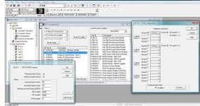
The configuration of RIO adapters is done with the "1747-SN G-file Configuration" window, which you have also shown.

The key to understanding Allen-Bradley nomenclature is to know that one "Logical Rack" is 8 "Groups", each of which has 16 bits of Input Data and 16 bits of Output Data.

My guess is that the eight-slot chassis you showed in "AdapterSide.jpg" is the one represented as "Rack 00", size 1/2 Rack.

You must make two changes:

1. For the 1747-SN Scanner Configuration, change the configuration of Logical Rack 00 from 1/2 to 3/4 Rack size.

2. For the 1747-ASB configuration, you need to change some DIP switches.

Set SW2-7 = OFF and set SW2-8 = ON to change the ASB Module Image Size from 4 Groups (1/2 Rack) to 6 Groups (3/4 Rack).

The configuration of the 1747-ASB module image size is shown on page 4-10 of Publication 1747-UM006. All Allen-Bradley user manuals are downloadable in PDF format from the literature.rockwellautomation.com website.

The new modules data will be in the SLC-500 I/O data table as addresses "I:1.4/00-15" and "O:1.5/00-15".
 
Last edited:
Thnk you very much ken

all i need to do is change these 2 settings.it will automatically configure new i/o modules

and
any problem by complementry mode?
 

Similar Topics

i need to communicate slc 500 with RIO and how i configure it thanks
Replies
6
Views
2,299
Due to all the recent icing from the great winter weather this past week we have experienced many power glitches. reaking havoc on our drive and...
Replies
5
Views
4,772
I am using SLC 5/05 processor with remote I/O's with 1746-ASB module. The remote rack has two RTD cards. One is working OK. The another has 4...
Replies
1
Views
5,888
I’ve searched the internet for answers on how to do this. But I’m in need of some help. I have a slc 500 connected to a RIO. There are two racks...
Replies
6
Views
1,139
I am getting an error on my 1747 - ASB that says NOC. I looked this up in the manual and all it says is no communication. Which I knew that lol...
Replies
3
Views
1,626
Back
Top Bottom