RSLogix5000 Bit Shft Left

ctg_00

Member
Join Date
Aug 2011
Location
new jersey
Posts
13
I'm having a hard time converting over (the tag nomenclature) from PLC5 to 5000. If I can get some help with the following, I'll be on my way:

I want to turn on 16 bits in sequence about a second apart using a 1756OA16 and a BSL. I've studied the tutorial but still have not grasped filling in the parameters of the BSL/Array. If someone could walk me through that block, I would be able to get the timing, etc.

The module is in slot 2. The outputs are wired up to an input module in slot one. I's basically for a dog n' pony show. The CPU is a L55 V16

I don't really need the alias' if I don't have to.

Thanks in advance.

CTG
 
CTG,

I can do it using RSLogix500, similar but not identical.

A dog and pony show? Usually I get more dogs than ponies!

Is this for training purposes or for a demonstration? The reason I ask is that BSL's are normally used to synch PLC memory movement with the physical movement of something. You seem unclear about what your bits are representing (what information they are moving from one time and place to another time and place).
 
It's a demo. All my boss wants is the outputs to light up in sequence and feed 110VAC to the input module. I'm a good PLC5/SLC500 guy, but have been away from programming for a number of years. I need to grasp the 5000 BSL Array concept. I'm reading the tutorials but it's like anything else. You really have to work with the stuff daily to get good.

Thanks,

CTG
 
All my boss wants is the outputs to light up in sequence and feed 110VAC to the input module.
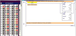
I have an RSLogix program in the can that makes interesting light patterns, if you want a copy. I can post a picture of part of it.

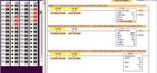
This one uses Sequencers (SQL and SQO) to generate XX number of different light displays, using two 16-bit output modules. The number of patterns is selectable, and all are guaranteed to be different (no repeats) until it cycles around to the beginning.

Here is a copy running on the LogixPro Simulator. I have it set here for 75 patterns, with Masks to allow use of only the first 12 bits of O:2 and O:4.

SEQUENCED LIGHT ARRAY R2.jpg
 
Last edited:
CTG,

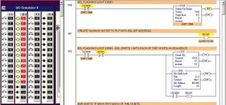
Here is a BSL Flashing Light program similar to what you requested. It shifts a "1" into a 16-bit Output starting at O:2/0, 1 bit at a time, then "reverses" using a BSR and shifts a "0" into each Output, starting at O:2/15 and working back to 0.

BSL FLASHING LIGHT DEMO.jpg
 

Attachments

  • BSL FLASHING LIGHT DEMO.pdf
    154 KB · Views: 167
Last edited:
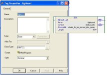
That is interesting. I'm having an issue with 5000 that gives me an error:
Verifying routine: MainProgram - MainRoutine...
Error: Rung 0, BSL, Operand 0: Invalid data type. Argument must match parameter data type.
Complete - 1 error(s), 0 warning(s)

Any suggestions?

Thanks,

CTG
 
CTG,

"Invalid data type" probably means that you typed in something that the PLC does not recognize as a memory address. I am guessing that Operand: 0 is the first entry in your BSL, so it is probably something wrong with the File Address. Notice that you must have a # in front, and it has to start at the beginning of a word address. You cannot use a constant (number) here for either the File or Bit Address - it needs to be a memory address. Also check to see that you did not type a "O" (character) in place of a "0" (number).

File is the address of the bit array you want to shift. You must use the file indicator (#) in the bit array address. You must start the array at a 16-bit element boundary, for example, use bit 0 of element #1, 2, 3, etc.

Control is the unique address of the control structure (48 bits, 3 16-bit words) in the control area of memory that stores the instruction’s status bits, the size of the array (in number of bits), and the bit pointer (currently not used).

Bit Address is the location of the bit which will be added to the array.

My LogixPro Simulator program may have caused you to not enter the # on the File Address. I just noticed that (although I typed in the #) that LogixPro automatically deletes # for all Output Addresses used in the BSL and BSR. It apparently is trying to force the user to enter an internal B3 address, even though O:2 still works without the #, and RSLogix has no such restriction on using Output words in the Bit Shift File Address instructions.

To prevent this anomoly happening to others, I modified the program to use #B3:2 in the BSL and BSR, and then added Rung 005 to move B3:2 to Output O:2. (See attached R1 version of the program).
 
Last edited:
Notice that you must have a # in front, and it has to start at the beginning of a word address. You cannot use a constant (number) here for either the File or Bit Address - it needs to be a memory address. Also check to see that you did not type a "O" (character) in place of a "0" (number).

Lancie, Since he's using RS5000 wouldn't he just need the tag for the array that he is shifting rather than a file address?
 
The tag is all that he would need, however he said he was not going to use "aliases", whatever that means.
 

Similar Topics

I've got a plant with around 500 different instruction-based alarms. The plant would like for the sirens and beacons to go off when any one of the...
Replies
14
Views
2,505
I really need your help here! I have a Decimal Number that is being transferred in 1-byte words. The original number is larger than 1 byte...
Replies
2
Views
2,370
Hi, done Cop(Copy) instruction but usually with DINT or INT in an array, but just happen an hour ago that I try to COPy an array of 380Boolian...
Replies
0
Views
2,085
I just got a fancy new laptop only to find out they still don't have RSLogix5000 ver 18 or 17 compatible with W7 64 bit, but "they are working on...
Replies
18
Views
14,861
Hi all, I'm new to rs logix5000. I'm trying to implement a shift register, like BSL.How do I generate tags for the control word and the array...
Replies
4
Views
10,172
Back
Top Bottom