I have a BIG problem with some PT 100 !!!!

stonez

Member
Join Date
Apr 2012
Location
Romania
Posts
16
Hello everyone, I have a project that I have to do, and it sounds like this.

I have to connect a PT 100 sensor to a plc, and write a program that will calculate after measurement, that the sensor is between its error limits, and maybe store the measurement data, so many sensors could be measured and tested.


Also I would appreciate if someone came and explained the steps in a very basic manner, I'm new to all this.

Thanx in advance.
 
Hi, and welcome to the forum!

Which PLC type do you (intend to) use?
And the AI- card type?
You know there are transmitters converting and linearizing a signal from resistance (PT100) to the 4-20mA industry standard?

Kalle
 
Hello Kallen,

Well I was thinking of S7-313c, or 314, or 315. (probably 313c)

LE: uff AI, I was thinking 6ES7331-7PF01-0AB0, or 7KF02....

Can you explain a bit more of the 4-20mA industry standard ?


(PS: I was thinking of testing the sensors with the plc connected to a laptop or something like this, but if you have a better solution please)
 
Last edited:
If the task is testing and certifying sensors, it must be defined how accurate measurements that is required. And then you could start to look for an analog reader that suits your needs.

Are you sure you cannot use a calibrator for the job? Google for Pt100+calibrator.

Also if you google 4-20mA, you'll find better explanations of this than I can give.

Kalle
 
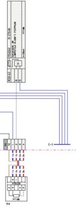
In the drawing have PT100/4-20mA transduser. AI-unit is 7KF02.

The transduser have set for 0-200 C, so 20mA means 200 C and it is
equal than +27648 in PEW262.

PT100.jpg
 
Are you sure you cannot use a calibrator for the job? Google for Pt100+calibrator. Kalle
Listen to Kalle, that's wisdom speaking. The description fits a calibrator with software.

The difficulty of using a PLC for calibration is that in any calibration, an accepted baseline is having a calibrator that is 4 times more 'accurate' than the device being calibrated. Calibrators are designed with this in mind. PLC's are not.

In English there's a saying about trying to drive a square peg into a round hole.

30hyosw.jpg


A calibrator is round peg, a PLC is a square peg.
 
(PS: I was thinking of testing the sensors with the plc connected to a laptop or something like this, but if you have a better solution please)
Is this a student project?
 
In English there's a saying about trying to drive a square peg into a round hole.

30hyosw.jpg


A calibrator is round peg, a PLC is a square peg.

Thats how wooden dowels are made.

This is clearly a project where a PLC is used to perform some task as an assignment.

Of course the PLC is not the best tool for this, unless you have a PLC and don't have a calibrator, or you want the system to run a self cal during run time. Maybe it would be usefull as a self check.

Some details to keep in mind:

PT100s are a resistive element. The change resistance based on temperature. Around 90 degrees F they usually read around 110 ohms.

You will notice some amount or increasing resistance with increasing temperature.

Some PLCs can read the PT100 or T/C directly in, some PLCs use an external transmitter to convert the resistive reading into a 4-20mA signal and read that into an analog input.

The wiring will also have resistance. Thats why the PT100 has 3 or 4 wires as a lead compensation.

Trying to read a PT100 at over 20 feet away without a transmitter will be difficult.

Either way you go, the temperature is just an analog input.

Then you need to scale the input. It's a simple formula.

Like 4-20 Ma = 1-5 V = 50-200 degrees F.

Or whatever your limits are.

4-1 means if the calibration requires 1%, then your standard needs to be at least 0.25%.

10-1 is ideal, 4-1 is minimum according to NIST / AGMC . ISO probably has this listed somewhere as well.

Once you fully understand all the details, you will be able to understand how to use the PLC to calibrate your sensors and why it might not be the best solution.
 
With 7KF02 analog unit can do it directly without 20mA transcucer.
Cable resistance is "constant" with 2-wire cable =f(lenght and wire area).
Correction can do in PLC-program if needed.

PT100 7KF02.jpg
 
With 7KF02 analog unit can do it directly without 20mA transcucer.
Cable resistance is "constant" with 2-wire cable =f(lenght and wire area).
Correction can do in PLC-program if needed.

I have never measured the actual length of any conductor that I installed. I imagine you could put an encoder on the wire feed and count the length, or install the wire, then pull it out and lay it straight and use a long tape measure. Or would you just walk it off in paces?

Then you would need to install a sensor every foot or so in the conduit to compensate for changes in ambient temperature........what would you use for that?

Then compensate for all that in the software I guess.

Orrrrrrrrrr use a 3 wire RTD with a transmitter mounted right at the RTD and then run the 4-20 whatever unknown distance back to the PLC.

Transmitter also gives you Zero and Span adjustments to set your range to match the PLC analog in.

"Cable resistance is "constant" with 2-wire cable "

in a vacuum, with constant conditions, and constant current applied, with known length. On paper.

I have never worked on anything like that though.

Of course if you just need "sort of close" temperature readings most of the time, that would work I guess.
 
We can use 4-wire connection as well as shown my drawing.
With 2-wire, I can measure cable wiring resistance, that is not real problem.
Eeconomical problem is unnecessary cost with 4-20mA transducer and its extra split in 4-20mA signal.
In my last project customer wants spend 800$ for those (9pcs) unnecessary transducers.
One problem is put PT100 sensor to right place, in worse placing split could be mats mats more than cable resistance.

Simatic Analog unit scales signal to e.g. x0.1 deg. units to (periphery) Input word.
Siemens have 8-channel AI unit for direct PT100 connection 6ES7 331-1KF01-0AB0.
In my drw exaple have 7KF02 unit who is in original question. 7KF02 unit needs 2-channel for one direct measure.
And, e.g. Beckhoff company have 6 differnt type of PT100 Analog input units.
 
Last edited:
We can use 4-wire connection as well as shown my drawing.
With 2-wire, I can measure cable wiring resistance, that is not real problem.
Eeconomical problem is unnecessary cost with 4-20mA transducer and its extra split in 4-20mA signal.
In my last project customer wants spend 800$ for those (9pcs) unnecessary transducers.
One problem is put PT100 sensor to right place, in worse placing split could be mats mats more than cable resistance.

Simatic Analog unit scales signal to e.g. x0.1 deg. units to (periphery) Input word.
Siemens have 8-channel AI unit for direct PT100 connection 6ES7 331-1KF01-0AB0.
In my drw exaple have 7KF02 unit who is in original question. 7KF02 unit needs 2-channel for one direct measure.
And, e.g. Beckhoff company have 6 differnt type of PT100 Analog input units.


Reading lead resistance over long distance is not reliable, but you could do it with an extra analog input and a wire RTD.

As for cost, how much does the transmitter cost?

How much does the extra analog in cost?

Is the resolution on the analog in enough to measure the differential resistance between the two sets of leads?

Will the usual wire nut connections change the lead resistance? Will the change be constant on all the connections?

Does the process need reliable control with close tolerance temp measurement?

There is always an alternative method, you just need to pick the compromise that suits the situation.
 
How many sensors and what is speed of reading needed.
How many wires the Pt100 have.
Why siemens it is expensive.
what are you controlling.
take a look at simpler cheaper controllers or PLC
beckhoff, WAGO, codesys
If no speed is needed with some simple relais you can get a good analog value of many sensors (when 4 wire) and only one analog input.
have a look at an XTR105 simple converter
 
How many sensors and what is speed of reading needed.

Good point.
Typically we can get 95% of temperature changing in one minute when sensor is inside same protection pipe!
When measuring from gas flowing, the temperature can be "what ever" depending where the sensor is.
What is Accuracy when controlling temperature e.g. to 0.5 degree difference between input and output of heat exchanger primary and secondary part. 4-20mA transducers calibration can be hard work for that purpose, so I pass them.

Also, outdoor temperature measure is not easy cake for wind, sun, south or north side the home. On my patio -south side- can be +20C and north side can be -2C at the same time. Our clocks are in summertime, but, everywhere have snow.
 

Similar Topics

after about a half day working with a rep from siemens today because I could not get my new tia portal ver 13 software to connect to a plc only to...
Replies
9
Views
4,613
Can u help me to build this program by using fpwing.gr?plss..i need it :( thanks if u can help me.. The PLC program simulates a process tank...
Replies
80
Views
15,226
hi my name is hamzeh baharvand from iran please help me . I have a big problem in plc honeywell ipc620-25
Replies
3
Views
2,089
Hallo Guys I tried to install RSLINX 2.59.02, so far so good. I started the insatllation yesterday evening and it still runs !! The EDS...
Replies
14
Views
7,277
Hi! Found this forum by accident and so far it seems to be active. :) PROBLEM: I want to use ARRAY OF BOOLs to determine which coils are set and...
Replies
1
Views
2,674
Back
Top Bottom