You are using an out of date browser. It may not display this or other websites correctly.
You should upgrade or use an alternative browser.
You should upgrade or use an alternative browser.
Plss help me.big problem for me
- Thread starter fidamin
- Start date
View attachment FIDAMIN'S TANK FILL PROBLEM-page 3.pdf]according to your diagram,if i press X3 so the alarm will silent right?
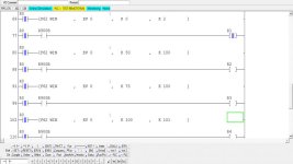
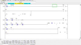
the situation is the alarm will ring as it exceed the 100% of water level.so if i press the X3 it will stop ringing.but i did on the fpwin gr the R6 not on when it reach 102% level of water as it exceed the limits.Here,you can check it as i attached the file..
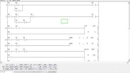
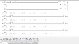

the situation is the alarm will ring as it exceed the 100% of water level.so if i press the X3 it will stop ringing.but i did on the fpwin gr the R6 not on when it reach 102% level of water as it exceed the limits.Here,you can check it as i attached the file..


Last edited:
Yes, R6 is only ON for 1 scan of the PLC (so that the alarm cannot be silenced more than 2 times). You probably cannot even SEE R6 turn on, because it will be very fast, probably ON for only 3 to 8 miliseconds. The ONE-SHOT DF is required by your project instructions. R6 is NOT the 102% Alarm Output. R5 is the "HIGH LEVEL SAFETY LIMIT" internal relay that shows 102% Tank Level has been reached, and it will be ON only until the SIMULATED tank level drops below 102%.The situation is the alarm will ring as it exceeds the 100% of water level. So if I press the X3 (Alarm Silence Pushbutton), it will stop ringing. But I did on the FPWIN-GR program, and the R6 (Alarm Silence One-Shot) is not on when it reaches 102% level of water, as it exceed the limits.
If you turn on PLC Input X2 (102% HIGH LEVEL LIMIT SWITCH), you should be able to see Y8 Output go ON, and also the internal R5 relay go ON. You might have to slow your simulator down and only do 1 scan at a time to see the Y8 "TANK HIGH LIMIT STROBE LIGHT" go ON.
I do not think there were any instructions that said HOW LONG the "TANK HIGH LIMIT STROBE LIGHT" had to stay on! A few PLC scans should be enough, correct?
No, I am incorrect, so you need to change your program to stop at 102% Tank Level, and not restart until you press START again.If the high limit is met at a preset value of 102% full the process will shut down and a strobe light will turn on.
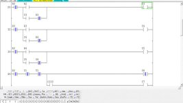
If you want the tank level to STOP at 102% so that you can SEE or HEAR the Y8 alarm, then you will need to change the program to stop it at Tank Level 102%. The current version does NOT stop at 102%, but immediately starts draining the tank, so that the alarm only stays on for a short time, probably only 2 or 3 PLC scans. You probably could stop it at 102% with the existing STOP button, but change your program to not RESET the F118 Counter on Rung 58, and not have R0 turn OFF R5 on Rung 112, until you press X0 START again. R5 should turn on the Y8 "TANK HIGH LIMIT STROBE LIGHT" on Rung 50, which gived the external high-limit alarm required by your program.
Last edited:
Yes, you could simulate part of it with those items. You would also need some devices for the Ultransonic Level Detector, and the High Limit Strobe Light, 50% Level Light, 75% Level Light, and 100% Level Light.very complicated
but it look interesting.
can we use air pump motor(aquarium pump) with hose,LED to detect level of water,water container and buzzer to do this project?
Here is version R1 that attempts to stop the simulator exactly when R5 HIGH LEVEL SAFETY LIMIT is ON. I added a REST BUTTON X4, so that you can continue after done looking and listening to the alarm horn.
The ZIP file has to be decompressed (extracted), and saved to your FPWIN-GR software "Documents" file folder, before you can OPEN it.
The ZIP file has to be decompressed (extracted), and saved to your FPWIN-GR software "Documents" file folder, before you can OPEN it.
Last edited:
Here is version R1 that attempts to stop the simulator exactly when R5 HIGH LEVEL SAFETY LIMIT is ON. I added a REST BUTTON X4, so that you can continue after done looking and listening to the alarm horn.
The ZIP file has to be decompressed (extracted), and saved to your FPWIN-GR software "Documents" file folder, before you can OPEN it.
I tested your program,the R1 and Y1 is only ON?
The rest R2,R3,R4.R5,isn't ON?
it's so complicated program.can u explain how it's working?
Jessua, I don't know if or how it runs on the PLC, because I do not have a Matshshita Electric PLC to test it.
Here is the original description of how it is supposed to work: (see attached file).
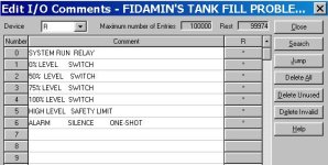
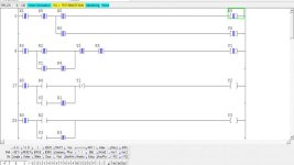
Looking at the program, internal relay R1 is "0% LEVEL SWITCH" so it SHOULD be on if the tank is empty and RO "SYSTEM RUN RELAY" is ON. Y1 is "TANK FILL VALVE", and it should go ON when the SYSTEM is in RUN mode, and the tank level is below 50%.
To make the program work, you will need the 5 Input switches, X0 to X4. Without those, it will not work properly.
Last edited:
I don't know what you have in your program. Please post a copy of the program you are running here, and I will try to help you find the problems. When is only R1 ON? When the program is first started, of course only R1 (the 0% LEVEL SWITCH) will be ON at that time. When the Start pushbutton X0 is pressed, timer TMX 0 starts running, the F118 UP-DOWN counter starts counting and counts above 0, causing R1 to go OFF.Why is only R1 only ON?
(2) The next level switch relay R2 WILL NOT and SHOULD NOT go ON for 50 seconds, until the F118 Counter hits "50". If it should go on BEFORE 50, then you have an error in your program!
(3) The next level switch relay R3 WILL NOT and SHOULD NOT go ON for 25 more seconds, until the F118 Counter hits "75". If it should go on BEFORE 75, then you have an error in your program!
(3) The next level switch relay R4 WILL NOT and SHOULD NOT go ON for 25 more seconds, until the F118 Counter hits "100". If it should go on BEFORE 100, then you have an error in your program!
(4) The next level switch relay R5 WILL NOT and SHOULD NOT go ON until the F118 Counter hits "102". If it should go on BEFORE 102, then you have an error in your program!
Your timer is not running, or your counter is not counting. Check Rungs 54 to see if R0 is ON, which should turn on Timer TMX 0. Check Rung 50 to see if Y1 is ON. If both these are true, then you have your program set up incorrectly, or you do not have your program loaded onto the PLC, or you do not have your PLC in RUN mode.I can't see the level of water rising.
What about R0? It is the SYSTEM RUN RELAY, and should be ON before anything else will work. If R0 is on, and the tank levels are not working, then the Function F118 UP-DOWN COUNTER is not working as described in the manual (maybe an error in the manual description about how F118 works). Check X4 to make sure that it is OFF while F118 should be counting. X4 should only go on when you want to Reset the counter to 0.R1 is processing/ 0% level only ON while the other output relays are not ON, as it increase 50%,75% and 100%.
That is all I know, because I have never used this PLC, nor have I ever even seen one with my own eyes!
Last edited:
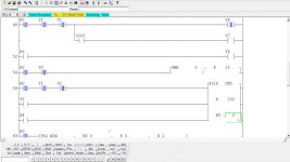
Okay, Fidamin, now you have given me something to help you figure out why it is not working. The counter is not counting, and apparently it is always set to "0", so looking at the manual, on Page 3-328, the Counter K102 top number is not actually transferred to the Counter Preset value UNLESS the counter reset operation is first done. So you need to insert a rung and add a parallel branch on the F118 Counter, below the X4 Reset button, and add a NOT R0 (--|/|-- RO). This should cause the counter to reset the counter BEFORE the SYSTEM R0 relay goes ON (and moves K102 to the counter preset memory area.The only outputs that are ON are outputs R0 and R1. The F118 counter up and down didn't count from K0 to K102. So the counter C100 isn't counting. F118 counter needs to replace as its not counting properly.
Question for you: Is the Timer TMX 0 running from 0 to 10 and then resetting? In your picture, it appears to be equal to "9" when you made the picture. If so, that is one step that is working. If the timer is not timing up to 10 x 0.1 seconds, then resetting, that can keep the F118 Counter from working.F118 Up-Down Counter
Precautions during programming
If the elapsed value area has been specified as a hold type memory area, the elapsed value acts in accordance with the contents being retained.
Be aware that, when an operation is begun, the set values are not automatically preset to the elapsed value area. To preset these values, the reset (bottom counter input) must be switched from the “on” to the “off” state.
Last edited:
Similar Topics
Hello, I need to write the following program in Ladder language, but I could not integrate the Fibonacci sequence into the ladder. Can you help...
- Replies
- 11
- Views
- 169
this a program to send data to barcode printer I want to integrate a new printer in a new machine and i wanted to adapt the old prgram on it but I...
- Replies
- 4
- Views
- 154
So i've been at this for a long while, i have Citect Scada 2018, i have full access to everything but i can't seem to find any option or...
- Replies
- 0
- Views
- 53
Hi all, hope you are having a great day,
I am in need of your help to create a AOI or program that does this kind of job:
I have a IO Link...
- Replies
- 26
- Views
- 477
please help me . I have to make this ladder diagram and I can’t figure it out :(
- Replies
- 12
- Views
- 362


