Simple Koyo Click Question

jli20

Member
Join Date
Apr 2012
Location
San Diego
Posts
11
Hey everybody,

I'm pretty new to PLCs, we had an old PLC set up for our machine and are currently replacing it. So basically, I'm trying to get a hang of the Click PLC by just testing a simple lighting of an LED on the machine. Now everything was working properly on the old PLC so all the wiring should be fine. I merely switched the output and the +24V on the machine from the old PLC to the Click PLC. However, the problem is the LED is not lighting with my program. I set up a simple normally closed variable to the LED output. I see the LED next to the physical output terminal on the PLC light up red but I'm just assuming that that means it's working?

Any help is appreciated.
Thanks!
 
You didn't mention the model of the Click but on the DC (not relay) outputs a connection to the output power supply common is also needed besides the plus side and the output itself.
 
Hmm, I have the C0-02DD1-D. So basically I swapped out all the wires from the old PLC to the Click PLC, exactly the way it was before, with the output common, +V, and the actual output. And the output doesn't seem to be activating the LED.
 
Was the 'old PLC' a Click C0-02DD1-D? If not wiring differs greatly between different PLCs and even between different models of the same PLC. Check the manual very carefully. Note that your Click has NPN outputs.
 
Last edited:
Download chapter 3 of the Click manual, paying close attention to page 3-28.

Better yet, post your circuit here.
 
Last edited:
I've read the manual but I'm still unable to get it to work. So I've tried activating the buzzer that is currently hooked up to the machine. There are two wires coming out of the buzzer, the positive is hooked up to the Y1 terminal and the negative is hooked up to the common terminal. I wrote a simple program in which normally closed C1 activates Y001, however the buzzer isn't turning on. From the manual, I got the impression that the output module powers the terminals, however I was not able to get a voltage reading across the module. Can someone guide me in the right direction? Sorry for being such a bother
 
Last edited:
Swap your positive and negative, also test your buzzer on the +/- just to make sure its working

y111.png
 
Last edited:
Sorry, it was actually originally connected as, negative to Y1 and positive to +V. I tried swapping either way and nothing is working
 
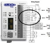
1. The Click output does not SUPPLY power it only SWITCHES an externally supplied source of power.

2. The circuits you are trying to power probably hooked their low side to the common and they were turned on by switching + power to their other lead. While there are those types of Click units this one works by switching the low side of a load.

3. Your buzzer, for example, will have its + side hooked to the + side of the external power supply and its - side will wire to the output of the Click.

4. Notice that, (referring to the diagram supplied by geniusintraining) in addition, the + side of the external power supply must be wired to +V and the - side of the external power supply must be wired to C2. This is necessary for the internal electronics of the outputs to work.

Good luck.
 
Here is a point to point outline of the procedure.
1. Connect the 24v power supply - terminal to terminal C2 on the PLC shown in post #7.
2. Connect the machine LED - to the Y1 terminal on the PLC.
3. Connect the machine LED + to the 24v power supply + terminal.
If the LED for Y1 on PLC is lit, your LED on the machine should be lit.

Edit:
What bernie said, he types faster than me.
 
Last edited:
Sorry, it was actually originally connected as, negative to Y1 and positive to +V. I tried swapping either way and nothing is working

If its a large one it may be more then the PLC can handle, you may need to have the PLC switch a relay then have the relay handle the load and make the buzzer, this is a better way to do it anyway
 
Thanks for all the responses guys. So I understand that an external source of power is needed to power the buzzer and that the PLC merely acts as a switch. But the machine's current setup with the old PLC (CTC 2200 http://www.ctc-control.com/customer/techinfo/docs/legacy/2200XMIG.pdf) is configured exactly the way I specified earlier. How come the buzzer turns on with just the negative on the Y terminal and the positive on the +V on the CTC 2200 without the positive hooking on to an external supply?
 
You did not specify the I/O card in the old system. The PDF you linked to is just for the CPU and backplane. However, if your I/O card is this then note that it has an internal power supply (as page 14 shows clearly) and the hookup as you describe is sufficient.

This emphasizes the importance of reading and understanding everything about a system before applying it. In your case it means that you must thoroughly understand both the old and the new system for a proper transition.
 
Thanks for the help. From the Click power supply specifications, I got the impression that once hooked to the CPU, it supplied internal power to the terminals because it says it supplies power to the Logic side as well as the Field Devices
 

Similar Topics

Hello again..trying something on an existing poorly written program and just wanted to double check something system is an A-B MicroLogix 1200 In...
Replies
5
Views
168
Hi all, Writng a FB in ST on Beckhoff TC for a pulser which turns on and off on a cycle, is paused by turning bControlInput to FALSE, but resumes...
Replies
6
Views
248
I'm trying to build my Classic Step 7 programming skills this weekend. I get stuck on little things that are not covered in YouTube tutorials. I'm...
Replies
7
Views
316
I have a program that does a 7 second "scan" sensor calibration routine whenever a setting (setting is called assistance level or "AL" and ranges...
Replies
3
Views
212
Hi all, I have a simple question that I have overcomplicated and gotten stuck on. I have a variable, we can call it "light" that I need to stay...
Replies
4
Views
313
Back
Top Bottom