Working on my Simatic Manager knowledge this weekend. Simple questions....

AutomationTechBrian

Lifetime Supporting Member
Join Date
Jul 2013
Location
St. Cloud, MN
Posts
669
I'm trying to build my Classic Step 7 programming skills this weekend. I get stuck on little things that are not covered in YouTube tutorials. I'm going to post a few here as I go along. Like this question:

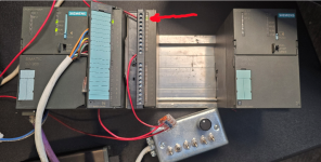
When setting up the S7-300 PLC in the Hardware Config, it asks the firmware version. I have a CPU317-2 PN/DP that I picked up on Ebay a while back. The setup screen asks for firmware version. I don't see that information anywhere on the nameplate. Is it asking me what is is now, or am I choosing what I want it to be?

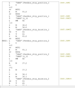
I'm going to be working on understanding STL, which is an on-going frustration for me. It seems completely alien to me. I have a remote connection to a customer's PG, which is connected to the plant's S7-300, and I'm going to try and learn what some of the mystery STL blocks mean. I suspect I'll start a new thread for that, once I get that far.

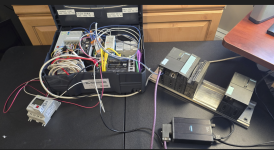
Just for the heck of it, here is my desktop learning lab setup. The case with miscellaneous PLCs is there for the power supply. I'm wondering if I have to wire the 24v to the I/O cards as well. Next, I'll throw some toggle switches on the Input card for the lab.
 

Attachments

  • PLC Lab.png
    PLC Lab.png
    1 MB · Views: 20
hi, STL is "steatment list" in german lang is =AWL.
on awl ... (ops for me is awl) the debug is frustation because also the ACC evalute the locic result (STA & RLO)... you'll find out by trying.
any case Siemens S7 Status Word | PLCdev

Have you get comunication?
Manager step 7 is not frendly software, normaly there is more on thing for get online.
If is first time for you, I advise to made hardware configuration with the more low relaease firmware on your software,
after download the configuration,
one box warning exit, is warning but in the box there is the version inside.
You can continue safely even if the firmware is not the same.

or you can follow the image (sorry but My interface is not in EN)

good luck
personally when I can stl (awl ) I still use it... it's very convenient and I write too much less :cool:
 

Attachments

  • __2024-03-16_22-47.png
    __2024-03-16_22-47.png
    88.7 KB · Views: 10
Yeah, I am online. I put in the lowest Firmware, 2.3, for that CPU. I checked what it says when the Hardware Config is online... V2.3.4. It seems I guessed right. I've just been playing around with the setup, trying different menu commands. The one bummer, it looks like my output card is bad. It was a used card when I got it, and it looks old, so it's not surprising. The diagnostic says it's OK. The output energizes in the program, but the output LED doesn't light. I'll get a meter out of my car and see if there is voltage when energized. I wired terminal 1 to +24vdc, and terminal 10 to the common. I didn't wire the second group of 10 terminals, if that matters.

About 25% of the blocks are written in STL. I also have to understand the GRAPH language, which seems much easier. I'll be creating some made-up programs to test each. It won't be as much fun without a working Output card. I'll use M bits for the coils, and do a watch window.

This is a random block from the program to show everyone what STL looks like.
 

Attachments

  • STL.png
    STL.png
    13.9 KB · Views: 16
Lift the door on your CPU and the firmware version should be painted above or below the communication ports.
You can also use Accessible Nodes and change the view to Details. FW is reported here, as I recall.

The hardware config is instructions to the CPU on how to behave and what to look for. The current-generation CPUs will happily work with a version specified lower than actual, but I have not tried with the 300s. Will probably work fine with a difference in minor revision.

STL is simple until you get to pointers and indirect addressing. A and O = "look for a one", AN and ON = " look for a zero". Place your cursor on a command and press F1 to learn about it.
There are a few specifics with the memory registers, but learning STL is really just looking behind the curtain of the way LAD operates.
 
Last edited:
Hi, It seems strange that the outputs aren't working.
2 considerations.
1) All the power points of the Input and Output cards must be powered, see the datasheet (google, siemens support, & etc..).
2)Look at the pictures, you have to check the address, in my case the card has the address is 123.
3) Put these lines in OB1 (main) so the outputs must go on, pay attention because my AWL is different from your STL, the language changes, I'm used to in German Lang... unfortunately something changes... but you use it as an exercise :).
See image
L AB 123 // load byte 123
INC 1 // inc the byte value of 1
T AB123 // trasfert to output 123 (the vale stay in Acc)
L B#16#FF // Load costant hex_FF
XOW //made xor in Acc
T AB 124 // Trasfert to output 123
BE // end absolute

===
for graph in step7 manager is different package or Program.
If you are more familiar with Tia Portal you can use tia portal. see image

1710671048773.png
 
Thanks for the reply. I'll be trying examples of STL today. A while back, I got a popular book on STL, "Automating with STEP 7 in STL and SCL", by Hans Berger. I'll be looking at his examples and trying to absorb as much as I can. The book had a downloadable file of examples (on page 8), but the webpage is no longer there. Bummer, I am a visual learner, and I get much more out of examples than reading. I did see some examples in Simatic Mgr. help file last night. I'll check that out, as well.

As far as the output card, as I was booting up my laptop this morning, I toggled my input, and the output LED lit. I don't know what happened, or why it didn't light up yesterday. I'm pretty happy about it, though.
 

Attachments

  • OutputWorks.png
    OutputWorks.png
    975.9 KB · Views: 8
I've got a copy of the Berger book mentioned above, £30 posted in the UK if anyone wants it.
 

Attachments

  • IMG_20240124_204741.jpg
    IMG_20240124_204741.jpg
    136.2 KB · Views: 3
  • IMG_20240124_204813.jpg
    IMG_20240124_204813.jpg
    112.6 KB · Views: 3

Similar Topics

Hi every one I want to connect the two stations in step 7 I have a CPU 315-2PN/DP as a master and the CPU 315-2 DP can any one help me by showing...
Replies
2
Views
1,407
I have a problem in a Simatic S5-115 cpu 944 with single PG port The machine worked plc has two IP240 cards. In the first card, the second...
Replies
0
Views
1,548
HI.Friends in my Simatic S7-200 CN CPU224CN Relay output Siemens PLC which is installed in a TOWER CRANE,output1 is not working,but all other...
Replies
10
Views
3,856
Hello. I have problem, with analog output card Simatic AO 8x 12 bit 6ES7-332-5HF00-0AB0. I m using all 8 outputs with 0-20mA.I have disconnecded...
Replies
0
Views
1,817
I am creating a project with WinCC Unified v16 Upd6 (PC runtime) with an S7-1200. The communication is good between the PC and the PLC as I can...
Replies
6
Views
196
Back
Top Bottom