ABB S4C Plus Restart

echambers

Member
Join Date
Aug 2012
Location
Alabama
Posts
10
I am sure most of you are also robot enthusiasts, I am familiar with a lot of the Motoman protocols for wiring but not familiar with the ABB system. I currently have an ABB that is being used in a welding cell.

There is a small operator station that operates doors and starts the robot. There is also a restart button on the operator station that has never worked.

I have been tracing wires down to find where this is connected to try to get this working but have found that someone in the past has pulled both wires that go to this button and wire nutted the ends.

Does anyone know enough about this system to help with where the signal would need to go to get the restart button working properly. Ideally this would restart the robot when any interruption (i.e. door being lowered by the operator during normal operation, or hitting an E-Stop.)
 
Where are they wire nutted together at? The controller or the PB? If they are wired at the PB you should be able to follow them back to the controller and see where they land. Probably on a combi-I/O as inputs.
This will give us some idea of how the system is setup.
If the reset was originally terminated at the board as an input. Just look at where it is terminate. Then you can use the EIO file as a lookup table and see how it was configured. This will allow you to back track where it is used in the programs. I setup a few of these years ago. I would have set them up as a task where you couldn't see them from the teach pendant. To many helping hands that wanted to play games and turn stuff on and off.
 
What protocol is being used to restart the robot from the “small operator station”? (Is it ethernet, devicenet, hard wired, etc.) It should be fairly simple to do once you know how the robot is being told how to resume operation. If it is stopped via an e-stop it becomes a little more complicated, the e-stop circuit will need to be reset with an e-stop reset command.
 
I bet the word "protocol" wasn't intended as a reference to the physical media but more the way the system is laid out.

In our house we have a certain "protocol" on how we handle disciplining our children. I don't mean using a large trunk device net cable to spank them with (y)
 
The reset button is set up as just a button on the operator station, the operator station has 4 buttons, door up, door down, cycle start and reset. It is wire nutted in the controller. Our plan was to put the robot back into operation (restart) once it was stopped by lowering the door to clean the nozzle in our welding application.
 
OK look at where it was wire nutted together does it look like there are 2 places that wires should land?
 
Look at the I/O board and see what terminals are not used.

You can also start looking in the program to see if it is used.
 
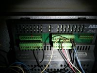
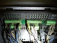
Here is a quick shot of my I/O boards. I have reviewed the I/O's listed in the controller and do not see any that look like a reset. If I counted right there are currently 14DI's setup in the controller.

robotio1.jpg robot io2.jpg
 
I would look over that program again and again. Is there a Mod Pause in the program once the operator opens the door the cell stops then the is that from the door input? If so look at what re-enables it. I have worked on a couple of systems that wouldn't let you open the door as long as the robot was in the protected zone.
The operator would press the door open and once the robot was clear of that zone it would open the door.
 
are those 327 boards on CAN BUS? isn't the top right hand connector the CAN terminals.
Your first picture shows that terminal as open.
It has been 6 or 7 years since I touched one from a setup side.
 
You appear to be correct on the CAN. Here is the exact order things are happening.

Start program,
Robot moves to side1
drop door
Robot stops, Errors come up Safety Guard Stop State, and Auto Stop Error
Raise Door
Error Stays (does not clear)
Clear Error (press OK)
The motors are off
Turn motors on
Push start to restart the program.

My back ground is with Motoman systems so I know little about setting this up, but would like to get it working properly.
 
Look in that job right before the error for the safety guard stop state and auto stop error . This should point you to what is stopping the system.

I would look at the e-stop chain on the main board and see where it goes. Probably through the door limits or some type of door switch. This could be a safety reset like mscholz said in post #3. If that is the case the it would be terminated on the main I/O board and not the add on boards.
 
When the door goes down AS1 and AS2 on the 509 board go out. when the doors go back up they come back on. It looks to me like from here the reset button will need to clear the errors, turn the motors back on, and start the program.

On the motoman this would be done in most cases with 3 buttons.
 
Get the wiring diagram for the 509 board.the motors on is usually in a task running in the background.
 

Similar Topics

hi i try to do a simple program displacement program using PDispOn PROC move_up_back() PDispOn *, tool1; MoveL *, v500, z10, tool1; PDispOff...
Replies
2
Views
2,046
Hello everybody, I am looking somebody with experience in ABB S4C controller. We have a robot that last weekend stops, later of many times to...
Replies
3
Views
3,445
Hello, I am new to Devicenet and I was wondering if someone out there could give me some advice. I have a ABB robot with an S4C+ that I need to...
Replies
3
Views
2,459
does anyone have an install or know if/where i can download it for the following "ABB PS501 Control Builder Plus V2.3 " the software was a free...
Replies
2
Views
89
Hello, It is mandatory to use VFD IF i use IE5 electrical motor? What happens If connect it directly as delta without VFD? Please look at motor...
Replies
1
Views
136
Back
Top Bottom