Safety Relay Reset Regs

robw53

Member
Join Date
Nov 2009
Location
south yorks
Posts
515
I am after a bit of info from anyone who is in the know about this but basically i am looking for a legal way to reset my pilz relay after an amount of time has passed, basically i will explain from the beginning...

so i have a pilz relay, and that feeds the safety contactor for several PF40's so what i want to happen is that as soon as the safety circuit drops out it cannot be reset within 20 seconds to allow the drives to power down and stop anyone resetting it too early, before anybody says it, yes i know that a PLC should not have any control over a safety device, but i have one way i believe could work but i would like some advice, the way i was thinking is to have the timer in the PLC and after it powers down and the 20 seconds has elapsed then when the reset button is pressed and brings on the input, then this gives the output to the safety relay for resetting, but this output would go through the actual reset button on a second contact block before it goes to the reset input on the pilz relay, this would then mean that if an output was stuck on then it would not reset the safety relay after the e/stop was removed, can anybody see any issues with this from experience maybe?
 
so i have a pilz relay, and that feeds the safety contactor for several PF40's so what i want to happen is that as soon as the safety circuit drops out it cannot be reset within 20 seconds

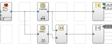
Have you considered the Pilz programmable safety relays, you can create time delays etc within the software - for example the reset for the E Stops occur as normal but the safety outputs operate after a time delay.
An indicator flashes to indicate reset in operation.

Although OkiePC has the correct solution.

Pilz.jpg
 
Last edited:
well this machine is one we are having built from the states for a new line, anyway, the reason i wanted to do it from the PLC and monitor the off period of the safety relay was that on this vendors older machine they have a solid state timer inline, with a 30 second delay, i dont like that as when they maybe open a guard to empty rework container and other guard doors then they maybe open for two minutes, once this is done then they have to wait a further 30 seconds even if the drives have been powered down for ten minutes, which is why i wanted to monitor the time from the safety relay dropping out.

okie, if i design any e/stop circuits i always go through the N/C contacts on the safety contactor, and the reason i say for the PLC output to go through the reset button is that if the contact on the output card failed, then as soon as the e/stop was reset then contactors would then automatically reset, but if i have to physically press in the reset button aswell then that means that no one single failure could power up the line automatically, as if the output stuck then i still need the push button to reset, if the push button stuck then code in the PLC for anti-tie down of the reset button, but if a reset button was stuck in on any safety circuit it would reset automatically if the reset went through the N/C contacts of the safety contactor.

to me its almost more of a safety risk by putting the reset circuit through the N/C contacts as if it was just an output or just a push button resetting the safety relay then the anti-tie down on the safety relay would detect this and would not reset until it saw the rising edge of the reset.
 
Hi rob

From a ce point of view and under the new machine laws once you document the reasons for why you want to do this there is actually nothing wrong with what you want to do, you could even wire the reset button to your plc input ( remember the reset must be a blue button) and have a output resetting your Pilz relay BUT and there is always a BUT. When you change the safety you now become the owner of the design of that safety curuit. This is not a problem as long as you are happy the curuit has a proper risk assement done and I would always mail your reason for changing ( which sounds like a good reason to me ) it and just make sure that he or she replys.

The other option which would cost a lot but maybe you could make sure it's done in the future is power flex drives with safe off again it's more wiring but it would also fix this problem.

Donnchadh
 
Last edited:
Hi rob


The other option which would cost a lot but maybe you could make sure it's done in the future is power flex drives with safe off again it's more wiring but it would also fix this problem.

Donnchadh

Useing drives with Safe torque Off normally reduces component count and wiring due to not normally requiring an output contactor. I say normally because it will depend on the performance level required from your safety circuit and the reliability figures for the selected drive. A couple of years back I did a 60 drive system to PLd with no output contactors.

Importing machines to Europe can be problematic from a safety perspective. I've seen many machines imported that do meet EU regulations and then need an expensive upgrade before they can be used. Will the OEM provide a Risk Assemsment and a Certificat of Conformity? Will the safety circuits be designed and documented to BSEN 13849?

Just some things to think about.

Nick
 
normally I use safety relays with a timed contact available.
this drops out the drive enable of the VSD/s first then drops the power after a timed interval.
by default the safety relay can only be reset once these contactors are out.
using a PLC to reset the safety relay - May Not - be a problem as the safety relay is measuring the time taken for the contactors to energise and the N/C contact to open.
If this was a problem then the reset button would require to be a Dual contact button. Depending on your requirements, think about this option.
one contact to the PLC the other in series with the PLC output.
may be overkill - but it is a posibility
 
Rob

Since you are using PF 40's why not avoid all that all together and just use safe torque off http://literature.rockwellautomation.com/idc/groups/literature/documents/um/pflex-um003_-en-p.pdf

It is built for this purpose and you don't need any contactors and all that mess.Simpl;y a better solution and using less components (points of failure)and less panel space.

I would not buy any new drives without it. It's my site spec and we love it. A lot easier to troubleshoot also.
 
maybe i am over thinking the PLC output through the conact block on the reset button and making things more complex but if the PLC output was to fail then if im correct that even when the emergency stop is released the safety circuit should not reset as the Pilz unit PNOZ S4 looks for the rising edge for a reset, even if you were to go through the N/C contacts of the main contactor.


The STO option are for the PF40P drives i didnt think it was possible to fit any STO to a standard PF40 inverter?

Rob
 
we have had discussions about using the new PF 525 drives, they aren't out over here just yet but im guessing as they are in CA he must have heard about them and maybe they are already available over in the states?????
 
Rob

If this is new equipment as Okie said it may be worth your buck to upgrade to a higher class of drive. The STO is done a different and much butter way in the 750 series.

At this point in time I would not be putting anything less than a 750 or 525 series in new equipment. The 40's 70's and some 700's are going to be rolling out to pasture much sooner than you think. Trust me.
 
I think we are two worlds apart, i couldn't imagine the issues I would have specifying PF 750's for a conveyor application, they would look at me gone out.
I'm not sure what the 525 cost in comparison to a PF40 with Ethernet card, but it's come a little too late the suppliers have already ordered and we don't even have them released over here till next month, I would like to get our manufacturer in California to maybe roll with these but again it comes down to cost, Cant expect him to absorb the difference when the RFP stated PF40's with 22-COMM-E cards.
 
I dont really get your issue here if you only want to disable reset for some time after safety circuit has tripped. Why dont you just drive interpose relay from plc that enables reset.

Im sure you have safety relay status wired to your plc, just use falling edge to start a timer and open that relay for that time. Its not like its any safety function.

Simplified:

RESET PB ResetOK relay Reset Input of safety relay
----| |-------------|/|-------------------o


PS. Okie started going ot from post 2. And that is what this thread have been after. Its another matter to have delayed contacts to open upstream contactor to have time for vfd's to stop. From this restart issue. Having delayed contacts is pretty basic thing i think. Also i prefer it to downstream contactors (STO ofc is best always).
 
Last edited:
Too much ot

Actually I was saying "You can't spend more but you can can buy better." Sorry AB fans, but you guys DO make great PLCs...

I recommend the ABB ACS355 series with STO option. You can buy them for half the cost of the comparable AB drive, they are compact enough to replace even the 160 series with support for many different networks.

What HP are we talking about?

Why don you go and make new thread for this. Its so far off topic.
 

Similar Topics

Good afternoon, I'm having issues resetting my safety relay. Sometimes it resets, other times it does not. We end up cycling power and hoping it...
Replies
9
Views
3,907
I have to install a reset button for a safety relay. Should it be a flush non illuminated PB or an extended head PB with guard or without guard...
Replies
2
Views
1,969
My questions are about ABB's safety relay JSBT5. A1 and A2 of course energize its coil. X1 and X2 are for stop reset. For this posting, let's...
Replies
5
Views
3,586
Hi, I am using AB 5069-L306ERS2 CPU. My system should achieve SIL-2. I have safety door switches connected to AB 5069-IB8S module, and I want to...
Replies
1
Views
108
Back
Top Bottom