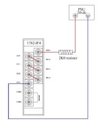
Test setup for a 162-IF4

With the internal resistance of each channel at 275 ohms, see picture below. The current will be about 8ma ( 7.7ma ).

I would prefer to test each channel and be able to vary the current up/down myself.

currentload.png
 
Ohms law!

Thanks for that Mickey I was forgetting about loading and ohms law, so if I drop the 2k resister and used 900ohm would achieve my 12ma 50% fsd!
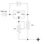
Git: cheaper option would be an LM317 at $2.50 2 diodes at 20c a resister at 6c and a 10k pot at $2.10 ! Aussie prices! total $4.86.

LM317.jpg
 
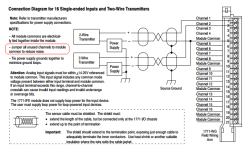
See picture below, its a snapshot of the manual for a 1771-IFE. I have seen this same note in other analog card manuals.

And a PDF for SLC input modules.

jumper.png
 

Attachments

  • jumper1.pdf
    35.6 KB · Views: 8
Last edited:

Similar Topics

Hi! I'm looking to design a test system that can measure a surface bend. I need to measure three positions. The sensors will be placed approx...
Replies
4
Views
2,353
I have looked through the other posts searching for “modbus S7”. The following variants of the CP 341 communication processor are available: CP...
Replies
25
Views
36,356
I go to test out a FFB instrument that is in a panel, not connected to FFB 'cause there isn't any here and I'm needing to ship it Real Soon to the...
Replies
2
Views
5,896
Hi, I am using M221 reading from 3 different sensors (modbus rs485) sharing same bus (daisy chain). I am currently using READ_VAR (in total...
Replies
0
Views
84
I am trying motor startup with pf525 drive by using wizard start over ethernet communication but during direction test it's showing control error...
Replies
3
Views
187
Back
Top Bottom