Confused about OTL

jgauthier

Member
Join Date
Sep 2013
Location
Miamisburg, OH
Posts
5
Greetings! I am very new to PLC programming and ladder logic, but I have some years of experience programming.

I thought I understood OTL, and that latching an output sets the bit high until it's unlatched. But in a program I wrote that does not seem to be the case.

So, I simplified it down, and was able to reproduce it.

Here is the diagram:
ladderlogic.jpg


A,B,C are exclusive. They cannot be on at the same time.
When I turn "A" on, the motor is energized.
When I turn "B" on, the motor is energized with latch.
However, when I switch to "C" from "B" the motor stops.

I'm confused about why, because I thought the latch would hold.

For those who have used LogixPro 500, this simulation can be executed in the Silo exercise.

Thanks! I appreciate the help in understanding.
 
That's because you used both a OTE and OTL instructions. This duplicate assignment programming won't work correctly.
 
I understand your words, but not why it doesn't work.
If I put this into words I read this:
If A then output
If B then output latch
if C then do nothing.

It seems like it should be very linear logic to me. I don't follow why it's duplicate when none of the conditions can be true at the same time.

Thanks!
 
Because the OTE will evaluate to false if A isn't true. Both instructions are using the same address.
 
Okay. I guess I thought that if A wasn't true it wouldn't be evaluated at all.
But I guess outputs are evaluated even if the condition to get to them isn't met?
 
I don't know the enter workings of LogixPro 500, but in a real PLC that last branch would never be accepted. You need an output instruction.
 
Okay. I guess I thought that if A wasn't true it wouldn't be evaluated at all.
But I guess outputs are evaluated even if the condition to get to them isn't met?

Relative to Motor, your code evaluates as:
If A Then Motor=1 Else Motor=0 ;
If B Then Motor=1 ;
 
If this is an "educational" scenario, fine. But in the real world, one should avoid the use of LATCH instructions whenever possible. Much better to write logic such that IF start button, ENERGIZE output. Then, back on the input side create a branch and use the SAME output address in series with if NOT stop button to hold the output true (set). That way the fact that the motor is running keeps it running until the stop button is pressed. And, without the latch, it prevents the motor from starting unexpextedly if say, the breaker was open and then got shut.
 
I don't know the enter workings of LogixPro 500, but in a real PLC that last branch would never be accepted. You need an output instruction.
Yes indeed.

It is at this point that the student says "you mean to tell me that the LogixPro simulator software does not work exactly like the Allen Bradley RSLogix 500 software"?

That is it in a nutshell. LogixPro is a simulator, not a duplicator. LogixPro is a pretty good approximation, but in cases where the student could be taught a lesson by leaving something out, the LogixPro author Mr. Bill Simpson chose to leave out certain RSLogix features such as giving the programmer an error message when he is making a logic mistake. Instead, LogixPro allows the student to type in the error-filled logic and try to run his program - fat, dumb, and happy! Then when the logic results in material spilled in the floor, or cars smashing into each other, or bottles crashing to the floor, that is when the buzzers and alarms sound, material piles up, big flames shoot up, and messages appear on the screen! It simulates how the programmer is going to feel when his bad logic hits the production floor!

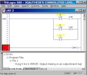
Notice that in the real RSLogix 500 version, the error message warns about the missing output on the output branch, but does not warn about how the bottom "C" branch could override the "A" and "B" branches if they all have the same output (the dreaded double-coil syndrome).

JGauthier's Convoluted Logic.jpg
 
Last edited:
I see that you are working on the LogixPro Silo Exercise 3, where you use the selector switch to choose the operating mode. You need to set up your Converyor Motor Output O:2/0 something like this, with only ONE version of the output, instead of 3. You only have ONE motor for the conveyor, and that motor only needs ONE PLC Output to turn it on or off. No latches are needed. (Latches should be generally avoided until you have more knowledge).

LogixPro Silo Simulator Exercise 3 Conveyor Output.jpg
 
Last edited:
It's not that the bottom leg with just a contact, if it were allowed at all, overrides anything. The result for the 'motor' output has been define by the precious two branches.

I think of the difference between OTE and OTL/OTU in this manner

The OTE has TWO possible operations. If the rung logic is TRUE then it turns the output bit ON. If the rung logic is FALSE then it turns the output bit OFF.

Each of the the OTL/OTU instructions only have ONE operation and that is only if the rung logic is TRUE.

For the OTL if the rung logic is TRUE the instruction turns the output bit ON. For the OTU if the rung logic is TRUE the instruction turns the output bit OFF.

It's not that the OTL or OTU have some special magic that makes the output LATCH. It is only that they do not have an operation when the rung logic is FALSE. They do nothing.

The latching through a power off/on cycle is due to the nature of the pre-scan. The pre-scan, in general - check the detailed operation under each instruction, evaluates each rung as if the final logic is FALSE. For an OTE the FALSE state turns the associated bit OFF. But for the OTL/OTU instructions they do nothing to the associated bit. Thus the presence of the OTE in the example would cause the associated bit to be turned off through a power cycle.
 
It's not that the bottom leg with just a contact, if it were allowed at all, overrides anything. The result for the 'motor' output has been define by the precious two branches.
What I meant was that when he gets around to adding the O:2/0 ouput to branch C (as I am sure that he means to do), then IT WILL override the top two when A or B is ON and C is not.

Besides, only one version of OTE O:2/0 is needed in this problem.
 
Last edited:

Similar Topics

Which of the following input operations require a conversion to digital form prior to input? a) disk b) analog c) contact closures d) limit...
Replies
12
Views
3,879
Hey all! I recently purchased myself a Panelview Plus off of ebay and i was hoping that i could upgrade the firmware on it to Version 9 or so and...
Replies
7
Views
2,744
Good morning everyone. I am apparently confused on the COP instruction. What I am trying to do is copy a DINT to a DINT in a User Defined Data...
Replies
16
Views
6,949
Hey guys, Im currently using the above flex IO to turn on two outputs these outputs go to two flashing red beacon lights. Here's the scenario: My...
Replies
4
Views
1,707
I'm event AV Technician (Sound, Projection, and Lighting). Over the last couple of years I've used a Weigl ProCommander PHX to control some event...
Replies
9
Views
2,696
Back
Top Bottom