Having a difficult time understanding theory of operation on Jordan Controls Damper

Rob S.

Member
Join Date
Sep 2008
Location
Maryland
Posts
739
I am having a incredible time understanding the attached drawing and the theory of operation on a Jordan Controls SM-1020-D-2 damper.

TB 2 terminals 3 and 4 is suppose to have 4-20 ma going to TB3 terminals 5,6, 7, and 8. TB 3 terminals 9 and 10 are the feedback 4-20 ma. I do not get
any 4-20 ma feedback with the present setup unless I place a 4-20 ma calibrator TB 2 terminals 3 and 4. What do you think influences terminal 3 - .

Would anybody know the theory of operation for this circuit ? I just cannot put my head around it.

Thanks in advance,
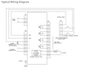
Jordan Controls SM-1020.jpg
 
Would anybody know the theory of operation for this circuit ?
The theory of operation would almost have to be about the same as any other damper that has 4-20 mA current input terminals. As the current on the terminals TB2 3 and 4 goes from 4 to 20, the damper operator motor will go from closed to open.

The optional wiring appears to be for a manual control station with OPEN and CLOSE pushbuttons. The circuit will be wired to allow max voltage to be applied to the motor in either Forward or Reverse direction. I doubt if the 4-to-20 signal goes to the optional customer-supplied control station - probably only voltage to the control PBs and back to the motor control circuit.

You probably will not get any 4-20 mA feedback current on the loop-powered TB3 terminals 9 and 10 unless you wire up the DC Power Supply and load resistor as shown (or connect to a external signal input loop with 24 VDC power). The feedback signal is shown as an option for Model MV-1005 control board, and your version might not have a position feedback signal (most damper operators do not).

The thing about these small stepper motor damper operators is if you wire one up wrong, you will burn out critical control parts and it will never work again. From the manual, the Model SM-1020 appears to have a 120 volt AC power input and a 24 VDC motor. The SM-1100 operators do not have overtorque protection. Overtorquing the actuator will cause permanent damage.
 
Last edited:
If I put a 4-20 ma calibrator on TB2 terminal 3 and 4 I get close to the same signal coming out of TB 3 Terminal 9 and 10. I also don't understand TB terminal 3 and 4. Where
there is not a physical wire coming off of TB 2 terminal 4 and just a wire coming off of terminal 3 going to the pushbuttons. Also , what are the symbols on TB 3 - 8 and 7 , 6 and 5 , 4 and 3 , 2 and 1 ? I know that 8 and 7 would stop the cycle at the closed max position and 6 and 7 would stop when it is open max. Also , what is the "Current command input 200 ohm shunt " ? That looks like a potentiometer. There is not a "Current command input 200 ohm shunt " in the circuit. If it was , what would be the purpose of it ?

Thanks
 
Jordan Controls is now part of Rotork. This actuator vendor is notorius for having a different wiring for every actuator that leaves the factory. They even acknowledge this in their manuals.

mcbxbl.jpg


I won't leave the shop for a Rotork job until I have the model number, serial number for the actuator and the exact wiring diagram because getting one out of customer service can be 2-3 day challenge.

All that vented, I'll comment on the wiring diagram you have, given that it might be half right and half wrong.

I suspect that the alternative TB3 'customer supplied contacts' and wiring for 'incremental control only' is for manual control, when a 4-20mA control signal is NOT connected to the unit. If you want 4-20mA control, do NOT wire the push button switches.

The wording "current command input 200 ohm shunt" means terminals 3 and 4 (TB2) are for a 4-20mA dc current control signal to the actuator. A dc current signal needs a dropping resistor, also called a shunt resistor. So the 200 ohm shunt does not refer to a potentiometer, it refers the actuators' analog input's input resistance. It's their method of saying that the device generating the 4-20mA control signal has to be capable of driving 200 ohms.

The position feedback 4-20mA signal is passive, loop powered, meaning it requires a 24Vdc power supply as shown, with your analog input being the load.

The designation LS means Limit Switch. The symbol appears to be an active output transistor, not relay dry contacts, as the description 'Low Level Logic Output' infers.

It appears to me that 4-20mA applied to 3(-) and 4(+), with line power applied to L and N should drive the motor, if the wiring diagram is actually that for your actuator.
 
Thanks for your help. We are using the "Customer Supplied Contacts". The contact on TB3 terminals 7 and 8 are actually going to relays to increase and decrease the damper.

Is the 4-20 ma on TB2 terminals 3 and 4 coming from the board level ? What you see TB2 terminal 3 goes to the "Customer Supplied Contacts" ( our relay contact ).

We do not have a "current command input 200 ohm shunt" on terminals 3 and 4 on TB2 . Should it have a 200 ohm shunt resister on 3 and 4 ?
 
Is the 4-20 ma on TB2 terminals 3 and 4 coming from the board level ?
No, TB2 Termianls 3 and 4 are INPUT terminals, and the signal would have to come from some other device such as a PLC analog output or a process pressure transimitter. In other words this circuit will not PRODUCE the signal but instead is looking for a signal.


What you see TB2 terminal 3 goes to the "Customer Supplied Contacts" ( our relay contact )...We do not have a "current command input 200 ohm shunt" on terminals 3 and 4 on TB2 . Should it have a 200 ohm shunt resister on 3 and 4 ?
Terminal 3 is "common" point to both the 4-20 mA signal INPUT and the circuit for manually controlling the operator motor with pushubtton switches (which is probably a voltage circuit that sends 24 VDC FORWARD or REVERSE (DC is reversed or not to motor) to make it run in the OPEN or CLOSE direction). Because you said this is what you are going to do, then you can forget about the 4-20 mA INPUT signal. You will not need that. Also you really don't need to know how the internal wiring connected to Terminals TB2 1, 2, and 3 works. It would be nice if you had the internal circuit and could figure that out, but all you really have to know is that if you connect the "INCREASE" and "DECREASE" toggle switch, it should open and close the damper operator.
 
PS: Thinking about other damper motors I have seen in the past, the motors usually have two windings with a common center connection point. (-) DC is applied to the center common point. + DC then can be applied to either the Forward or Reverse winding (from the operator controller board or from manual switches). Usually there are some internal limit switches that are connected between +DC and each winding, so that the motor will stop in either direction when it hits and adjustable limit switch.
 
Lancie,

Good description of an actuator motor; applying power to one winding drives it CW, applying power to the other winding drives it CCW.

One point: actuator motors run on AC, probably because DC requires brushes (maintenance) and rectifiers that are another point of failure.

The smaller low and medium torque Honeywell Modutrols and Invensys (former Barber Colman) EA series use a small AC synchronous motor that drives a humongous gear train to get usable torque. They each run from AC transformers. The motor models rated for line voltage operation have an AC transformer under the cover.
 
It has been 30 years since I worked on some at a wood-fired boiler system. I remember that some were operating from 120 VAC and others (Johnson Control brand I think) were operating at 24 VDC. We had to be careful and not get the AC and DC actuators mixed up because they looked the same on the outside.
 

Similar Topics

Good Morning , I'm new to the Siemens LOGO software. Have any of you had a problem downloading this Software from the Siemens website ? I...
Replies
5
Views
1,179
I have an Allen Bradley temperature switch that I am trying to use in studio 5000. I am getting the message "Unable to interpret the IODD file"...
Replies
0
Views
64
I copied a panel in factory talk HMI for an identical system. The label names are still the same as the original panel but I am trying to change...
Replies
1
Views
131
Hi All, Firstly… Merry Christmas to all of you! Secondly, as some of you may have noticed I made some modifications to our backend to address...
Replies
29
Views
7,085
Hi Everyone, I am supporting a system which runs on a SLC 500 (1747-L532). A fault has developed whereby the output state of some digital outputs...
Replies
10
Views
997
Back
Top Bottom