Connection Inside Motor Terminal Box

shawnhimself

Member
Join Date
Oct 2006
Location
LBC
Posts
84
I am starting to use a wider range of motors and noticing not all motors come with connection terminals inside the terminal box (peckerhead for you lay people 🍺)

What is most widely accepted way to connect your motor wires inside this box when you are not supplied built in terminals?

(Fair bit of a room in there, 10-100HP motors)
 
I see nothing wrong with wire nuts if the conductors are small, like up to AWG.8. And always be sure to tape the connections well after nutting. Larger connections I would use a split bolt, followed by a layer of vinyl tape, a layer of rubber splice tape then another layer of vinyl. If done properly you will never have an issue.
 
By "way to connect", do you mean the actual wire-to-wire connection ?

While I see a lot of twist-on wirenuts with tape wrapped around them, the NFPA specifically calls this out as unacceptable.

Edit: Chapter and verse from NFPA 79, 2007:

13.5.9 Motor Connection Boxes.
13.5.9.1 Motor connection boxes shall enclose only connections
to the motor and motor-mounted devices (e.g., brakes,
temperature sensors, plugging switches, tachometer generators).
13.5.9.2 Electrical connections at motor terminal boxes shall
be made with an identified method of connection. Twist-on
wire connectors shall not be used for this purpose.

13.5.9.3 Connectors shall be insulated with a material that
will not support combustion.
13.5.9.4 Soldered or insulation-piercing–type connectors
(lugs) shall not be used
.

I don't use crimp-on wirenuts because virtually all of my machines will need to be disconnected once or twice before final installation, and I hate losing an inch of motor lead every time.

My preferred method is to use ring lugs on both sides, connected together with a steel screw/lockwasher/nut and wrapped up in self-bonding tape.

Raychem GelCap splices are really good for larger motors, but most of mine are little so I stick with ring lugs.
 
Last edited:
We crimp on ring terminals and bolt the ring terminals together with steel bolts. On most smaller motors those are covered with T&B MDBOOTs. These boots are reusable for the most part and work really well.
 
I will agree, insulated ring lugs with steel bolts and planty of electrical tape. Same method i use on transformers with wire leads, I rarely use wire nuts.
 
As an ex-electrician gone rogue EE, I was trained, in the industrial sector, to do the following, and these methods are based on decades old principals of reliability and serviceability. Different from other connections, motor connections are EXPECTED to vibrate quite a bit, hence the ban on "wire nuts". There are two acceptable methods now.

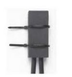
A) The "modern" method is to use pre-made motor terminals, often called "Polaris connectors" because they are the most popular brand. If you google an image of them, you will see what I mean. Many companies now offer them besides Polaris and they are all likely good.

B) The "old fashioned" way I was originally taught, which uses common items an electrician was expected to carry at all times, which if you can't get Polaris connectors, you should learn to do to avoid getting delayed.

1) Ring tongue crimp terminals on the ends of the leads, making sure you use the PROPER crimping tool per the terminal mfr. Since the connection will end up insulated later, don't use the insulated crimps, the insulation plastic can cause the tool to slip to one side and cut strands or not crimp tight enough.

2) Steel fine thread machine screws, nuts, a flat washer and a lock washer. Because of the vibration a lock washer alone will bite into the softer copper of the terminal and over time, might lead to failure.

3) Wrap the bolted connection with varnished cambric splice tape. The purpose of this is to facilitate future easy removal of the insulation because this tape has no glue so when you cut the other layers off next time, you don't have a mess. Remember, motors need periodic removal and refurbishing, so you are thinking of the NEXT guy who might be laying on his back in greasy dirt trying to get the tape off; and that guy just might be you! A common sort cut if you don't have varnished cambric tape is to use black electrician tape "backwards", meaning sticky side out, so the glue is not on the bolts.

3) Rubber "splicing tape", 3M #88 or equal, 3 layers minimum. Rubber tape helps ensure that if the connection touches the side wall of the box, it will take a lot longer for the vibration to wear through the tape.

4) Plastic "electricians tape", 3M #33+ or equal, 2 layers, on top of the rubber tape to keep the rubber tape from unraveling.

Lots of people take shortcuts of course, but this is the RIGHT way to do it.
 
I will agree, insulated ring lugs with steel bolts and planty of electrical tape. Same method i use on transformers with wire leads, I rarely use wire nuts.

even if you use a lot of layer, the electrical tape will wear against cover and make short to ground after a while even worst if it is on industrial environnement with vibration.

my last issue with this and a VFD was last year, i started a 75hp machine installed by a local guy with tape. It started fine and let him go in the morning but in the afternoon, i got a VFD failure and figured out it was the tape...The wire connection was rubbing against the cover. I got lucky because the vfd was protected against that but on a normal starter it would have been another story...

You need rubber or something harder for rubbing than just tape and make sure the wire are bend to remain in the middle of the box..(Using the cover to push them in isn't good)

BTW i think American design never has terminal bloc while it seen more common with Europeen ones but not sure...
 
Last edited:
The Polaris connectors look nice. Might try to find a supplier nearby.

Always good to hear the varied opinions, while wire-nuts are most likely sufficient I think they have a negative stigma when people see them.
 
when i see wires nuts on motor leads i expect to see a guy the we called in french a ''house cable puller (14/2-12/2 awg)'' instead of an industrial electrician but ...i may get negative comment on this...:)
And i agree that it could do the job on small motors for a long while without any issues
 
I use Burndy multitaps.

CUnitap3PortDS_Photo_ColorRGB.jpg


Been trying to eliminate wire-nuts from the facility - not going to completely happen but I try and keep them from being used on anything new.
 
Last edited:

Similar Topics

Softstarter "inside delta" connection. Why only for some kind of softstarters ? Electrical topic: I am pondering which softstarter for a...
Replies
19
Views
12,301
Hi dear . I have a system with cj1m cpu11 etn. previously NT 5z HMI was connected with plc. recently my old HMI got damaged. I want to replace it...
Replies
12
Views
246
Hello gentlemen, Im working on a small project on TIA Portal, about establishing a Modbus TCP connection between my ET200SP plc and a socomec...
Replies
12
Views
305
Hi all, My ethernet port on my laptop recently broke and I was hoping to just use a usb-c dongle in the mean time to go live on my PLC until I...
Replies
14
Views
453
Not a PLC question but I need expert help on this. My FactoryTalk stopped communicating with the server its hosted on. I had an error stating...
Replies
0
Views
106
Back
Top Bottom