You are using an out of date browser. It may not display this or other websites correctly.
You should upgrade or use an alternative browser.
You should upgrade or use an alternative browser.
PLC ladder Program
- Thread starter Hani Abdullah
- Start date
harryting
Lifetime Supporting Member
Hints:
A problem like this requires you to think of states / sequence. Start with defining states then moves on to define what cause the system to move from one state to another.
A problem like this requires you to think of states / sequence. Start with defining states then moves on to define what cause the system to move from one state to another.
Hani Abdullah
Member
OP
Sor could you please elaborate a little? I still cant understand it
harryting
Lifetime Supporting Member
I can start the state definition for you, you can finish it..
Let's call it state A as the initial condition and B for the second condition:
so
[A] = all lights off
= Light 1 ON, all other off
[C] = ??
get the idea?
Let's call it state A as the initial condition and B for the second condition:
so
[A] = all lights off
= Light 1 ON, all other off
[C] = ??
get the idea?
here is one attached program that serve your needs. I wrote it using simatic step7 for siemens. i hope that it helps you. you can test it on simulator
View attachment togell sequence.zip
View attachment togell sequence.zip
Hani Abdullah
Member
OP
Yes sir. I am still working on that software.
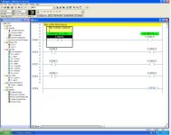
I have tried that and i got the following results but its not correct i guess. Could you please help me out Sir.
https://docs.google.com/file/d/0B8-F1xIJzzGVM2lGaHdwcmVMUDQ/edit
I have tried that and i got the following results but its not correct i guess. Could you please help me out Sir.
https://docs.google.com/file/d/0B8-F1xIJzzGVM2lGaHdwcmVMUDQ/edit
Because you cannot use timers or counters, you need a substitute for a counter. Use a "word address" N7:0 as a Step or Position Pointer. Each time your Step Switch I:000/3 goes ON, ADD 1 to N7:0. (Math instructions were not forbidden)!
Use comparison instructions (<, =, >, LIM) to turn on the Pilot Lights when N7:0 = Step Number.
When I:000/3 is ON, use a One-Shot ONS B3:0/0, and Add 1 to N7:0
When N7:0 = 1, OTE O:000/05
When N7:0 = 2, OTE O:000/04
When N7:0 = 3, OTE O:000/03
When N7:0 = 4, OTE O:000/02
When N7:0 = 5, Do Nothing: OTE B3:0/1
When N7:0 = 6 OR I:000/06 is ON, Move 0 to N7:0
Last edited:
Hani Abdullah
Member
OP
Sir can please help me with the simulation on the software? Or can you help me drawing it on excel. Also can you specify my mistakes that i did here?
Hani Abdullah
Member
OP
Sir Can you help me with the simulation design or something like it please?
Hani Abdullah
Member
OP
Hani Abdullah
Member
OP
Can you please upload it again? Its not showing the whole image
Hani,
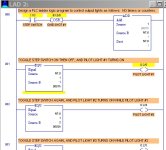
I am sorry, but your logic will not work. First, your instuctions say that you only have TWO switches, I:000/03 STEP, and I:000/06 RESET. You have used 3 Inputs that your problem did not allow. Go back to my Post #9 and #12 and study the logic and duplicate that in your program.
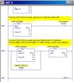
Well I will be nice and have pity on the sad, helpless, hopeless students. Here are the last 2 rungs in RSLogix5.

I am sorry, but your logic will not work. First, your instuctions say that you only have TWO switches, I:000/03 STEP, and I:000/06 RESET. You have used 3 Inputs that your problem did not allow. Go back to my Post #9 and #12 and study the logic and duplicate that in your program.
No, and I did not mean to show the whole image. I think that you should be able to figure out the rest for yourself, if you read Post #9 again. There are only 3 more rungs (000 to 006).Can you please upload it again? Its not showing the whole image
RSLogix5 has some differences from RSLogix500. In RSLogix 5, for your Rung 000, use a ONS instruction, address B3:0/0.Here is the picture of it sir. Its in RsLogix5
Well I will be nice and have pity on the sad, helpless, hopeless students.

Last edited:
Similar Topics
HEY there, could someone please answer this
Design a plc ladder diagram to control a production line of filling bottles with two conveyors upper...
- Replies
- 6
- Views
- 2,270
Dear All,
i am a computer engineering student and this is my last semester. part of my design project requires me to connect gsm modem with plc...
- Replies
- 5
- Views
- 7,457
V
I have no software to programming. My PLC rack contains CPU200H/SP001/OC225/OC225/OC225/OC225/ID212/ID212/ID212/.I have a console programming and...
- Replies
- 14
- Views
- 11,401
Hello,
I am trying to find a good source to learn about Graphset. I am not sure if I am spelling this correctly. I have been told that it is...
- Replies
- 1
- Views
- 10,950
I have a machine which is undergoing upgradation. As part of the process two SEW drives are being replaced., existing Gen B with new Gen C. The...
- Replies
- 3
- Views
- 197


