Is it possible to program this onto a Click PLC? If so, I need help anyway.

Okay, I keep asking this: how long does it take to get up to some pressure? Minutes? Seconds?

Does the operator tweak the knob, then wait (how long?) for it to settle, and repeat?

If it's a pressure regulator, then I don't think it matters how fast it is turned, and the only reason to turn it slowly is to avoid too much overshoot when approaching from below.

If I were the impatient operator, I would have the regulator set to max, and then when it gets close I would turn it to 0 quickly, over time and experience I should be able to gauge the in-flight.

The knob is literally a manual pressure transducer. As you turn the knob it let's more and more pressure in. He tweaks the knob a bit and the air driven pressure increases. It takes less than a second for the pressure to settle, then he turns it again and again untill the pressure gauge on the water side reaches the required amount.
It takes less than a minute to get to pressure manually. You can hear the pulses of the compressed air entering the pump every second or so as the operator turns the knob.


Okay, I think you said you are a mechanical engineer, so you know that turning the knob does not let "more and more pressure in." That said, I understand the metaphor.

I am pretty sure that knob is attached to a pressure (reducing) regulator, and that knob's position determines the setpoint of the regulator i.e. the steady pressure of the air that drives the pump.
 
Okay, I reworked pretty much the whole thing and made some assumptions that might be invalid.

Is the analog output that controls the test vessel pressure going to behave like an analog pressure command would or is it going to be more like a speed command to a pump that is pressurizing a closed vessel? I wrote the program such that there are two scale factors for the pressure command, one for the pre-test step and one for the pressure test step. Both scale factors are accessible on the HMI, and there is no logic to auto-correct them, although that could be done later. If the analog output acts like a rate command that controls the rate of pressure increase rather than the actual pressure, then you will want to start out with the "Test Scale Factor" setpoint to a much lower value than the "Pre-Test Scale Factor".

Is the dump valve normally open or normally closed? The grainger link said normally open, but I read in this thread somewhere that one of the valves is normally closed.

You said you were connecting serially from the HMI to the PLC. I set up the HMI to PLC link as Ethernet. Should be easy to switch if you really want to use serial, but I don't do much with C-More, so it might be harder than I think.

I think this program will function, but I can't test it easily unless I convert to a Click Plus and swap the I/O around.

Also, I changed the scaling of the analog inputs to milliamps rather than percent and turned off range limiting. This, (with a Click Plus anyway) will let you catch an open circuit and allows the HMI to show the raw signal in user friendly units if you are verifying a signal with a calibrator. I included a first order filter for the pressure signal with an HMI adjustable filter constant. I didn't find where in the C-More to setup data entry limits, but you want to clamp that filter constant between 0.001 and 1.0.

Before used in the logic, the filtered milliamp signal gets converted to psi.

I made the sensor range (2000 psi?) an HMI tag.

I'm sure this will need more work, but I think it's a better skeleton to build from and fill out the rest of the meat.

I did the HMI program with C-More software v 6.73
 
Last edited:
  • Subroutine 1 Sequence Logic, Rung 6, bottom branch can never evaluate to True: DF6 Real PSI Value cannot be simultaneously less than or equal to DF18 Low Pressure Tolerance AND greater than or equal to DF17 High Pressure Tolerance, unless the HMI Pressure Setpoint is non-positive.
    • So those compares need to be in parallel (logically ORed), not in series (logically ANDed).
  • I am curious how the system is filled with water and the air purged before the test begins.
  • Steps 40 could be eliminated and its logic folded into step 30:
    • In the Test Logic for Step 30
      • the counter logic (Rung 6) stays the same
      • if the pressure goes outside the tolerances, then SET C4 Test Failed Message
      • if the timer expires AND the value of C4 Test Failed Message is not 1, then SET C3 Test Passed Message
    • In the Sequence logic
      • on Rung 1, replace the final [DS1 Sequence Step = 40] branch with this logic
        • IF (step is 30) AND (test passed OR test failed),
      • i.e. in ladder:
        • [DS1 Sequence Step = 30] (first sub-branch) [NO C3 Test Passed Message] (second sub-branch) [NO C4 Test Failed Message] (join sub-branches)
    • The advantage would be that a test that fails early would not wait for the timer to expire.
    • But it may be easier to read as is, with step 30 to run the test and step 40 to evaluate the test.
    • perhaps adding an [IF (step is 30) AND (pressure is outside tolerance) THEN assign 40 to the value for step] rung/branch to the sequence logic would be simpler.
 
Quote originally by Brian:

  • The advantage would be that a test that fails early would not wait for the timer to expire.
  • But it may be easier to read as is, with step 30 to run the test and step 40 to evaluate the test.
I think the latter, that way the difference is easy to see so may give some indication of the problem, also, not sure if that HMI has graphs but it makes sense to trend the pressure on a test so you could see in realtime if it was a slow or quick leak, how much etc. Just for the OP's information, do initial tests on a known good part, this will help identify as lot of information for example if a known good part then any leak could be through the test equipment valve or coupling etc. It will also give you a good feel for the changeover & speed (air supply) to the system when 100% and the slow %.
Then try some faulty parts to make sure it is working as expected, for example think about an overall time for the system to get to pressure, if not then alarm because it could be a faulty part or some leak elsewhere this is especially important if for example under a normal test with a good part if it took 4 mins to get to pressure including the slow portion then if it was taking 10 mins or never got to pressure it could indicste the part is faulty or with a leak it may not reach pressure on slow pressure as the losses may be greater than the low speed casn replace it.
One company I worked for we did a number of different tests this included a vacuum test, this basically did the opposite of your system a vacuum was drawn to a set vacuum, left for x time & if the vacuum dropped it had leaked from the sealed pack, a loadcell system that put pressure on a sealed pack & we measured the amount of deflection, a good pack would give a few mm, a leaky pack would give larger deflection & a completely bad seal would give more, also no little pressure but no large deflection would indicate that the pack had not trapped the nitrogen/C02 in the pack. All these were logged to graphs for QA to analise.
 
Okay, I think you said you are a mechanical engineer, so you know that turning the knob does not let "more and more pressure in." That said, I understand the metaphor.

I am pretty sure that knob is attached to a pressure (reducing) regulator, and that knob's position determines the setpoint of the regulator i.e. the steady pressure of the air that drives the pump.

The knob is connected to a compressor that is at a constant 130-140 psi or so. There is a huge compressor upstairs that powers all our other tools and equipment in the shop. The knob is connected to an flexible air line which is connected to the main air supply of 140 psi and on the other side of the knob is the pump. So, when that knob is closed there is 140 psi at one end ready to start pushing into the pump. I am not sure if the knob lets flow in or just a certain amount of pressure in, if it works by letting a certain amount of pressure in every slight turn of the knob then it will be easy to implement the transducer, all we need to do is divide the theoretical output pressure we want by 16, then we know what pressure the transducer must output to make the pump stall. @drbitboy, you explained that I need to do a bit more calculating other than just using the pressure ratio, because we want the transducer not to go straight to stall, we want it to slow down to a stall. I didn't really understand how I was going to code a slow steady increase in the transducer so I will spend most of my time trying to find the easiest and most reliable way of doing it. You referred me to one of your posts a while back and I am not sure if I am that confident in coding something that complex, at least it looks complex to me. This feel like this code should be as simple as possible to make it easy to read and understand and also cause no bugs or glitches, since this is a pressure testing unit. At the same time there are better ways to code things that are a bit more complex, like trying to code the transducer to slowly build pressure until the transducer output causes a stall in the pump at the pressure we want. So I will take some time and really evaluate and build off of okiePC code and will change things here and there for the specific purpose. I will make sure I try to use most of the things I have learned here and reuse the things that worked the best.
 
Last edited:
Okay, I reworked pretty much the whole thing and made some assumptions that might be invalid.

Is the analog output that controls the test vessel pressure going to behave like an analog pressure command would or is it going to be more like a speed command to a pump that is pressurizing a closed vessel? I wrote the program such that there are two scale factors for the pressure command, one for the pre-test step and one for the pressure test step. Both scale factors are accessible on the HMI, and there is no logic to auto-correct them, although that could be done later. If the analog output acts like a rate command that controls the rate of pressure increase rather than the actual pressure, then you will want to start out with the "Test Scale Factor" setpoint to a much lower value than the "Pre-Test Scale Factor".

Is the dump valve normally open or normally closed? The grainger link said normally open, but I read in this thread somewhere that one of the valves is normally closed.

You said you were connecting serially from the HMI to the PLC. I set up the HMI to PLC link as Ethernet. Should be easy to switch if you really want to use serial, but I don't do much with C-More, so it might be harder than I think.

I think this program will function, but I can't test it easily unless I convert to a Click Plus and swap the I/O around.

Also, I changed the scaling of the analog inputs to milliamps rather than percent and turned off range limiting. This, (with a Click Plus anyway) will let you catch an open circuit and allows the HMI to show the raw signal in user friendly units if you are verifying a signal with a calibrator. I included a first order filter for the pressure signal with an HMI adjustable filter constant. I didn't find where in the C-More to setup data entry limits, but you want to clamp that filter constant between 0.001 and 1.0.

Before used in the logic, the filtered milliamp signal gets converted to psi.

I made the sensor range (2000 psi?) an HMI tag.

I'm sure this will need more work, but I think it's a better skeleton to build from and fill out the rest of the meat.

I did the HMI program with C-More software v 6.73

Thank you so much. I will start to edit things and hopefully get something out to you all by next week. I hope this next program will be way better organized than the others, and I don't mess up somewhere on simple Boolean logic or don't think about the scan cycle. There are some things in this new program that I don't understand, like when converting the psi values and also finding output values to the transducer.
 
Last edited:
I am not sure if the knob lets flow in or just a certain amount of pressure in


if the knob "lets flow in," i.e. if it is just a valve (e.g. a needle valve), then the source air pressure at 130psi would always push air into the volume upstream of the air-driven pump. So if the pump were stalled, then that air pressure - downstream of the knob/valve and upstream of the pump - would increase until it was enough to cause the pump to take another stroke, and that would repeat until the pump was stalled with the air feed at 130psig and the water pressure was somewhere between 1820psia (=130psig*14) and 2080psia (=130psig*16). If that is what the knob controls i.e. a valve, then only way to stop increasing the pump discharge water pressure is to completely close the valve.

But your description seems to indicate that the pump discharge pressure, once the pump stops, is a function of the knob position. That strongly suggests that the knob controls the setpoint (the spring inside) a pressure regulator. A pressure regulator controls a valve to make up whatever air is used (by the pump in this case) to maintain the air pressure downstream of the regulator i.e. upstream of the pump.

Since the I/P transducer is also a pressure regulator, the control details will be identical to what they are for the knob; the transducer analog output value, which is equivalent to the knob position, will be controlled by an automatic algorithm. It could be a simple ramp e.g. increase air setpoint pressure by 1/4psi per second, which would yield up to 4psi per second rise in the water discharge pressure.

Cant I just go test and see manually what the scale factor for the pump is? The scale factor should be 16 thought right, since the pressure ratio is 1:16? In that case all I need to do is program a reliable way to linearly increase the pressure in the transducer to the pressure it needs to be. I will try and use that method, maybe by putting a 1 second counter and connect it to a math command that will keep adding lets say 0.5 psi to the transducer, and once the desired pressure is met then it will stop, and should theoretically be very close to the pressure we want.
 
Last edited:
You could try to set the output to 0-16 or what ever is the rough scale for example lets assume the pressure guage the operator uses is 0-200 psi or 0-100% or kpascals, or bar it does not matter, you just go to the analog output setup in the PLC hardware & set the 4-20ma to what ever scale you want, it may not be exact as manual guages are not meant to be that accurate but it will probably make more sense to the operator, the analog input from the pressure sensor should be pretty accurate & if the sensor range is 0-200 psi or 500 psi it should be scaled to that.
So if you wanted it could be scaled in cups of cofee an hour. the point is that any real value will be converted to what the raw analog is like 0-4000 or 0-16384 or 0-32767 it will give the relevant output of 4-20ma.
Yes you could add the pressure in increments of lets say 0.5 just remember that you could alter the timer (use a variable for the pre-set & have an engineering page on the screen protected with a password so only engineers can have access, also remember to add a compare in the rung that adds the value to the analog output word so when it reaches the max it stops adding, so for example

Create a oneshot reciprocating timer
AND NOT Timer T3 out Timer T3 1s // creates a one shot (only on for one scan every second)

SEQ = 10 AND Pressure < 32767 AND Timer oneshot ADD 0.5 to Analog_Out. Sorry I cannot show actual code as I do not have Click here. You have to use a one shot or if the timer is on for more than one scan then it will add 0.5 10 times in one second, if one second is the timebase you are going to use then you could use the one second in-built clock but use the contact with the up arrow (this is a oneshot symbol i.e. it only triggers for one scan when the contact is on.

By raw analog you mean the scale? On click for inputs it shows the input range for the current, which for me is 4-20 mA, then it goes to scaled range. For scaled range I could just put 0 to 2000 (because my sensor goes from 0-2000 psi) which would represent the psi. Then I have to convert the scaled to a real value? But if the scaled is the real value can I just use that? Same thing for outputs but backwards a value comes in and it needs to be converted to scaled, if the value for the output needs to be say 20 psi for the transducer we need to convert that to scaled and then the PLC will convert it to analog and send the signal to transducer.

If the scaled range is exactly the right values, so for the transducer it's 3-120 psi = 4-20 mA and also for the pressure transmitter 4-20mA=0-2000 psi why would I need to convert to real value? Does the click PLC not automatically convert it to scaled? And also I can use that scaled number for other functions right? I don't need to change to a real number, if so idk why.

I am looking at okiePc code and the input mapping does not make sense at all to me, what is a filter? I thought the click PLC automatically converted the analog input from pressure transmitter into the scaled value, which would be the correct pressure in psi?

The main thing I am stuck on now when trying to edit @okiepc code is looking at the inputs and outputs for the transducer and pressure transmitter, he is doing a lot of math with numbers and addresses that I can't wrap my head around. I would appreciate it if someone elaborated more on how exactly the click PLC gets inputs and converts them, or if it does not at all, what do I need to do to convert it to a real value or analog value and why?
 
I would appreciate it if someone elaborated more on how exactly the click PLC gets inputs and converts them, or if it does not at all, what do I need to do to convert it to a real value or analog value and why?


You are an engineer, you should already know this, but here is one approach to explaining it. Search this forum for scaling and you will find more.

TL;DR


NCP2-20-3120N ( pressure transducer, current to pneumatic transducer)- https://www.automationdirect.com/ad...o_pneumatic_(i-z-p)_transducers/ncp1-20-3120n

On that page it infers a 4-20mA signal will result in regulated pressures of 3-120psig. That is,

  • a 4mA signal will yield 3psig (bottom of range)
  • a 20mA signal will yield 120psig (top of range)
  • a 16mA =(4+20)/2) signal will yield 61.5psig (=(3+120)/2)) (halfway point of range)
  • a 7.2mA (= 4 + (20-4)*20%) signal will yeild 26.4psig (= 3 + (120-3)*20%) (20% of range)
  • etc.
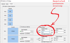
Now, a 3psig air pressure (4mA signal) driving the pump will yield a discharge (water) pressure of at most 3*16 = 48psia = 33.3psig, and a 120psig air pressure (20mA signal) driving the pump will yield a discharge (water) pressure of at most 120*16 = 1920psia = 1905.3psig.

Since everything is linear, you could simply scale the analog output like this:
Untitled.png

And then write whatever pump water discharge pressure you want to DF1, and the I/P transducer and pump will "make it so."


Caveats

  • Those numbers are not exact because do not reflect the actual instrumentation, but with calibration you could find the correct numbers
    • E.g. with experience you might find that the pump typically stalls a pressure ratio of 15.x.
  • This is not ideal, and there would be some benefit, e.g. flexibility, to making the calculations in the PLC program, but this general approach would work.
 
Last edited:
You are an engineer, you should already know this, but here is one approach to explaining it. Search this forum for scaling and you will find more.

TL;DR


NCP2-20-3120N ( pressure transducer, current to pneumatic transducer)- https://www.automationdirect.com/ad...o_pneumatic_(i-z-p)_transducers/ncp1-20-3120n

On that page it infers a 4-20mA signal will result in regulated pressures of 3-120psig. That is,

  • a 4mA signal will yield 3psig (bottom of range)
  • a 20mA signal will yield 120psig (top of range)
  • a 16mA =(4+20)/2) signal will yield 61.5psig (=(3+120)/2)) (halfway point of range)
  • a 7.2mA (= 4 + (20-4)*20%) signal will yeild 26.4psig (= 3 + (120-3)*20%) (20% of range)
  • etc.
Now, a 3psig air pressure (4mA signal) driving the pump will yield a discharge (water) pressure of at most 3*16 = 48psia = 33.3psig, and a 120psig air pressure (20mA signal) driving the pump will yield a discharge (water) pressure of at most 120*16 = 1920psia = 1905.3psig.

Since everything is linear, you could simply scale the analog output like this:
And then write whatever pump water discharge pressure you want to DF1, and the I/P transducer and pump will "make it so."


Caveats

  • Those numbers are not exact because do not reflect the actual instrumentation, but with calibration you could find the correct numbers
    • E.g. with experience you might find that the pump typically stalls a pressure ratio of 15.x.
  • This is not ideal, and there would be some benefit, e.g. flexibility, to making the calculations in the PLC program, but this general approach would work.

Just to let you know I am a mechanical engineering student. This is in second semester of my second year and instead of school I am doing co-op so I am interning at a place for a whole semester and then I go back to school. I never had a programming class once but I will be taking one next semester though, right now I am kind of glad I am on this project. If I can pull this off, then it will be good experience and also another skill that is useful to me as a mechanical engineer.

Okay I figured it worked like that and it was that simple. The reason why I asked that question is because okiePc did a lot of math and equations to convert the pressure transmitter input into a pressure. Not sure why he did that but I could simply convert the 4-20mA input straight to scale and use that value as the pressure of the vessel.
 
Last edited:
Ah, student, eh?

Well, 80-90% of what you will do as an engineer will be scaling in one form or another. So make sure you develop a keen sense of proportion.

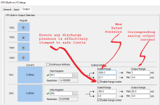
Also, that pump (Haskell 4B-14) has a maximum rated discharge pressure of 1500psig, so it should never reach the 1900psig+ of my previous post. We could consider enforcing that limit in the Click analog output scaling (see below; I'll leave the calculation of the corresponding max output current, in mA, to the student ;)). This unit will have a relief valve protecting it, but belt and suspenders never hurt anyone when it comes to safety. N.B. for that matter, there is no guarantee that the pump will be the limiting max pressure constraint.
Untitled.png
 
okiePc did a lot of math and equations to convert the pressure transmitter input into a pressure. Not sure why he did that ...

I can think of at least one good reason why @OkiePC did that in the PLC program instead of in the I/O menu: experience.

At some point there will be a calibration, or perhaps repeated calibrations over the life of the system. Or perhaps the characteristics of the pump and/or I-toi-P regulator will change over time.

By having HMI-accessible constants available to, and performing the calculations in, the PLC program, it enables creation of a calibration screen* in the HMI. So if any characteristics of the process change (e.g. degradation over time, or a replacement pump or I-to-P transducer), the program can be updated for the new conditions.

* probably write-protected from operators but available to the engineer,
 

Similar Topics

Hello. I have been trying to crack this one without success and could not find any hint after several search attempts. I wonder if any CODESYS...
Replies
4
Views
3,933
Hello, I'm pretty sure I know the answer to this, but wanted to verify with the experts. Am I able to write a program using the Micro Starter...
Replies
7
Views
3,161
First off, i am new to ladder logic. I do have some experience programming microcontrollers in C. I will try and give a short version and if more...
Replies
7
Views
2,024
This is a CompactLogix L33ERM, version 30 (31 is too unstable on my machine to work with), with a Kinetix 5500 drive. I have a program where...
Replies
2
Views
2,009
Good morning guys! I have a doubt. I uploaded a program from a S7-200xp on the field and took it to the office. Before doing any test I tried to...
Replies
7
Views
2,156
Back
Top Bottom