Mitsubishi Q series: Q68AD-G module - does it supply voltage to the connected device?

Mas01

Member
Join Date
Oct 2020
Location
Leicester, England
Posts
1,109
Sorry for the basic question...

I've had a look through the Q68AD-G (analogue input to digital converter), and I'm trying to find out if the module provides 24v to the connected device.
In my case, the device is a water level indicator which works off 24v. It sends a 4-20mA output back to the PLC. The PLC converts this to a digital value 0-4000.

Does the module provide the necessary voltage to the device?
 
In my experience, analog input cards often do not provide the loop power required to power two-wire devices (analog output cards often do source power to the output devices). You would typically wire from a terminal block with 24VDC to the positive(+) terminal of the transmitter, wire the negative(-) terminal of the transmitter to the positive(+) of your PLC analog input, and connect the negative(-) of your analog input back to the DC power supply common.

I couldn't find anywhere to download a manual or datasheet for that specific module, so I could be wrong, that's just typically how two-wire transmitters are wired to analog inputs.

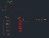
EDIT: I added a little screenshot of a typical wiring diagram that shows the connection between the card, transmitter, and power supply using terminal blocks. The blue coloured wire is the +24VDC, which is supplied to the + of the transmitter, the green is the signal from the transmitter coming out of the - terminal and going to the + terminal of the analog input, and the red wire is the DC common coming out of the - terminal of the analog input and going back to the - terminal of the 24VDC supply.

2Wire.JPG
 
Last edited:
In my experience, analog input cards often do not provide the loop power required to power two-wire devices (analog output cards often do source power to the output devices). You would typically wire from a terminal block with 24VDC to the positive(+) terminal of the transmitter, wire the negative(-) terminal of the transmitter to the positive(+) of your PLC analog input, and connect the negative(-) of your analog input back to the DC power supply common.

I couldn't find anywhere to download a manual or datasheet for that specific module, so I could be wrong, that's just typically how two-wire transmitters are wired to analog inputs.

EDIT: I added a little screenshot of a typical wiring diagram that shows the connection between the card, transmitter, and power supply using terminal blocks. The blue coloured wire is the +24VDC, which is supplied to the + of the transmitter, the green is the signal from the transmitter coming out of the - terminal and going to the + terminal of the analog input, and the red wire is the DC common coming out of the - terminal of the analog input and going back to the - terminal of the 24VDC supply.

Link to specification
https://www.manualslib.com/manual/1298499/Mitsubishi-Electric-Q68ad-G.html
 

If you look under section 1.1 - Features:

(3) Power supply to 2-wire transmitter (Q66AD-DG only)
Supplying power to the 2-wire transmitter, the Q66AD-DG does not require the power
supply for the 2-wire transmitter.
Supply power can be switched ON/OFF channel-by-channel by the A/D conversion
enable/disable setting.

Looks like you will need to provide power separately.
 
In my experience, analog input cards often do not provide the loop power required to power two-wire devices (analog output cards often do source power to the output devices). You would typically wire from a terminal block with 24VDC to the positive(+) terminal of the transmitter, wire the negative(-) terminal of the transmitter to the positive(+) of your PLC analog input, and connect the negative(-) of your analog input back to the DC power supply common.

I couldn't find anywhere to download a manual or datasheet for that specific module, so I could be wrong, that's just typically how two-wire transmitters are wired to analog inputs.

EDIT: I added a little screenshot of a typical wiring diagram that shows the connection between the card, transmitter, and power supply using terminal blocks. The blue coloured wire is the +24VDC, which is supplied to the + of the transmitter, the green is the signal from the transmitter coming out of the - terminal and going to the + terminal of the analog input, and the red wire is the DC common coming out of the - terminal of the analog input and going back to the - terminal of the 24VDC supply.

Thanks for this, the picture's really helpful.
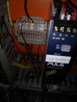
I suppose I could connect into this 24v power supply inside our PLC cabinet. See picture.

IMG_20220107_081843.jpg
 
@mylespetro Thanks for the help - I got the water level sensor connected up to the PLC with your helpful explanation. All working now. Cheers
 
@mylespetro Thanks for the help - I got the water level sensor connected up to the PLC with your helpful explanation. All working now. Cheers

Glad to help! Understanding different kinds of analog transmitters and how they're wired is pretty important, but fairly simple. Here's a pretty good diagram from an Allen-Bradley analog input card manual that I came across yesterday that shows the different types pretty well:

4pa2KXl.png


This is a little simplified, but illustrates the differences pretty well in my opinion.

That's a really useful little picture. Cheers.
 
Glad to help! Understanding different kinds of analog transmitters and how they're wired is pretty important, but fairly simple. Here's a pretty good diagram from an Allen-Bradley analog input card manual that I came across yesterday that shows the different types pretty well:

4pa2KXl.png


This is a little simplified, but illustrates the differences pretty well in my opinion.

Surprising that's an AB diagram!
 

Similar Topics

how to communicate FactoryTalk Optix and Mitsubishi Q Series. I want to know the details of that
Replies
0
Views
36
In this sample programming, what does U4 mean? Any assistance would be greatly appreciated.
Replies
8
Views
273
Hi, I have a project with a R04CPU, RD77GF16 and a RJ71PN92 modules. The cell is given to me to change the program since the previous integrator...
Replies
9
Views
288
Hi One of the PLC's that I maintain/update is a Mitsubishi Q-Series, probably installed about 10 years ago. At the moment, ALL the wires from...
Replies
13
Views
1,171
Back
Top Bottom