Mitsubishi Q-Series/GX Developer: How do I Expand the IO of an existing PLC...

Mas01

Member
Join Date
Oct 2020
Location
Leicester, England
Posts
1,109
Hi

One of the PLC's that I maintain/update is a Mitsubishi Q-Series, probably installed about 10 years ago.
At the moment, ALL the wires from ALL the field devices come into the PLC cabinet - typically, they'll snake their way there through ceiling cavities and holes in bricks etc.
These field devices wires are typically 20-30 metres long.

Honestly, the PLC cabinet is bursting at the seams in terms of the 100's of wires inside the cabinet. Adding more signals would be a nightmare.

Now the manager has said "We need to add 20 more analogue inputs and about a dozen thermocouple signals to the PLC. Can you do that for us?".

My first response was "yes, but it won't be easy. There's tons of wires in the cabinet already and the trunking is filled with wires"

Then my second thought was "Maybe we can use profinet or something. Then just bring a single profinet cable into the PLC cabinet."

As this is all new territory for me, does anyone have a "shopping list" of Q-Series-compatible items I would need to buy to do this system expansion?

I *think* I would need a Q-series CC-Link module? Which would be fitted on the DIN-rail in the PLC cabinet, plus some "local" IO modules close to where the new signal wires are located [?]

Any advice welcome.
Happy to expand on any of the above.

Thanks in advance.
 
Last edited:
You can use CCLink QJ61BT11N card with CCLINK cable and remote modules. Analog is a little more setup, but can be done.

CCLINK IE may be a better option with faster communication speed and easier setup. It uses QJ71GF11-T2 and standard CAT6 Ethernet cabling.
 
You can use CCLink QJ61BT11N card with CCLINK cable and remote modules. Analog is a little more setup, but can be done.

CCLINK IE may be a better option with faster communication speed and easier setup. It uses QJ71GF11-T2 and standard CAT6 Ethernet cabling.

Many thanks for this.
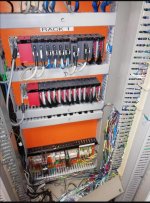
Funny you should mention the QJ61BT11N card. I remember seeing one on a PLC course I attended and I took this picture.
What's the red cable? Is that mitsubishi-specific cable?

IMG_20220811_164751.jpg
 
Long time ago, but the last one I used you need a CC link card in the main PLC rack, then use the remote I/O stations
Here is a link

https://dl.mitsubishielectric.com/dl/fa/document/manual/plc/sh080394e/sh080394er.pdf
I would contact the Mitsubishi rep they can normally talk you through the best option.
If I remember correctly the remote I/O coms card is a QJ61-BT11, the remote I/O modules connect by the 2 wire link & look like a small brick PLC's but they are just remote I/O not sure if these are still availlable but perhaps a later version.
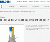
The cable only needs to be a shielded 2 core I think type cable nothing special just 485 type link but the better the cable & lower transmission speed possibly the cheaper cable
 
Last edited:
Ah.. That's right 3 core belden, couldn't think of it, after all it was 20 years ago, The one I was involved with had 8 PLC's, connected with NETH, Ethernet to Scada on main PLC & 12 CC link remote I/O modules, 14 ASI modules probably over 2000 I/O, so your system should be easy.
 
One other possibly cheaper way is if you have enough space at one end or on top of the panel is to use an expansion rack in a seperate panel, I think you may be able to buy an extra long expansion rack connecting cable, I have done this on siemens, just a thought.
 
One other possibly cheaper way is if you have enough space at one end or on top of the panel is to use an expansion rack in a seperate panel, I think you may be able to buy an extra long expansion rack connecting cable, I have done this on siemens, just a thought.

Not a bad idea, there's a bit of space under trunking "F" but there's 2 lots of 5"-deep trunking conduits on the left and right wall and they're rammed solid with wires.

IMG_20220808_150924.jpg
 
Last edited:
Yes I can see that, but what I was thinking is if there is space outside of the panel i.e. left right or on top then the only cables you need are power & rack connecting cable, just a couple of holes between the existing panel & new one, all the other connections would be in the new sub panel, have done this a few times myself. It would all depend on the space round the existing panel which I cannot see in the photo. only things you have to watch is obviously power requirements possibly use seperate power supply for 24v & care in cutting holes so you do not get metal shards in the existing components. I do suggest you get Mitsubishi rep to talk to you, they will be able to give you the best options & costs which ever way you go. There is a fare amount of I/O there so expanding the program it would be prudent to check the CPU type & memory capacity/ Spare ram.
 
Yes I can see that, but what I was thinking is if there is space outside of the panel i.e. left right or on top then the only cables you need are power & rack connecting cable, just a couple of holes between the existing panel & new one, all the other connections would be in the new sub panel, have done this a few times myself. It would all depend on the space round the existing panel which I cannot see in the photo. only things you have to watch is obviously power requirements possibly use seperate power supply for 24v & care in cutting holes so you do not get metal shards in the existing components. I do suggest you get Mitsubishi rep to talk to you, they will be able to give you the best options & costs which ever way you go. There is a fare amount of I/O there so expanding the program it would be prudent to check the CPU type & memory capacity/ Spare ram.
Ah, understood, cheers.
In fact the cable that I've labelled with the green arrow is an extension cable that goes to another cabinet on the left through a drilled hole (with plastic guard strip on the circumference to protect the cables) and there's 2 more racks in the cabinet to the left. But there's not much space in there because of other hardware and PCs. Above the cabinet might be possible though. I'll have a closer look next week. Cheers.

Screenshot_20231110_212256.jpg
 
Last edited:
Hi there
We also make use of Q25H CPU’s. What we started doing is to make use of IFM IO Link master in the field with Digital input, Digital output and Analogue module connected to the master.
We make use of Modbus TCP/IP coms between the IO link master and the PLC sing the QJ71MT91 plc module.
 

Similar Topics

On our PLC we've got a HMI where the operator can enter a target rotor speed in RPM. When target speed is enabled, M70 = TRUE. Then the operator...
Replies
19
Views
2,828
As per title, looking at how to scale an input, 4-20mA to a real value. Taking it in as an integer (RAW data)and converting it to a real, being...
Replies
0
Views
2,028
Hi all, weve just moved over to Mitsubishi GX IEC Developer 6.01 with the Q-Series PLC, used to have Allen Bradley SLC 500 Series & RS Logix, my...
Replies
4
Views
3,407
hi! i started to use the gx iec developer two years ago (now using ver. 6.01). about 6 months ago i started to programm q-series plc´s (mitsu)...
Replies
0
Views
4,220
hi! i started to use the gx iec developer two years ago (now using ver. 6.01). about 6 months ago i started to programm q-series plc´s (mitsu)...
Replies
0
Views
7,525
Back
Top Bottom