Mitsubishi Q series/GX developer...target speed RPM

Mas01

Member
Join Date
Oct 2020
Location
Leicester, England
Posts
1,109
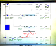
On our PLC we've got a HMI where the operator can enter a target rotor speed in RPM. When target speed is enabled, M70 = TRUE. Then the operator presses a "raise speed" or "lower speed" physical button to increase the rotor speed. I THINK the idea is that the "raise speed" button is inhibited when the target speed is reached.

From the code, can anyone work out what is going on? Operator tells me that 'enable target speed has never worked properly - or they're not sure how to use it, and prefer to reach the target speed manually.
IMG_20220304_090635.jpg IMG_20220304_090521.jpg
 
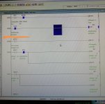
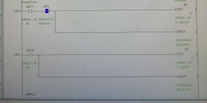
The problem is that some of the code is not in your pics, for example M71, however, it does appear it is meant to work from what I can see if the speed is below the Max speed then it allows the speed to be increased & the same for speed reduction.

Also the program is very messy & contains more code than is needed.
Is the speed reference i.e. target speed fed back as actual speed
The bottom two rungs where the compares are done is purely to limit the output to the minimum & maximum speed.
It seems weird that the inhibit bit M71 is only in the increment how is this bit controlled.
 
The code is not only overly complicated, as @parky notes, it is also probably flat out incorrect.

I'm not expert with GX Dev, but if I assume that T refers to a bit that is temporary (i.e. its value at the start of the scan is indeterminate) and M refers to a stored bit (i.e. its value at the start of a scan will be the same as it was at the end of the previous scan), then the images below implement what I would guess was the original intent (the PLC cares not a whit what you want it do, but it will faithfully do exactly what you code it to do).

Notes

  • The logic on the branches of current rung address 1960 could be moved to the upper branch of current addresses 1910 and 1917, but that might be too cluttered.
  • The top image implements a couple of one-shots to detect rising edges (transitions from 0 to 1) of inputs (push buttons?) X217(SPEED INC PB) and X216(SPEED DEC PB)
    • I have no idea how this relates to an HMI
      • Huh. unless the HMI is physical. Duh on me.
    • I would hope the inputs are debounced somewhere else.
  • The second image has logic to
    • either increase the internally-scaled speed value by 3 on the rising edge of X217,
    • or decrease the internally-scaled speed value by 5 on the rising edge of X216.
  • If you use the compare, [<...] and [>...], instructions at rung address 1960, then rung at (current) addresses 1986 and 1992 can be removed.
    • Doing that would allow this HMI-driven increase and decrease logic to slightly exceed the min and max limits in D458 and D456.
  • While I am sure I have duplicated the logic in 1960 regarding what is present at address 1986, I am not sure about the rationale for that logic involving Y2E5:
    • it currently prevents the HMI (or anything else) from assigning a speed reference value below the minimum (D458) when [Y2E5 EMERGBRAKE ON] is 1,
      • and allows the the HMI (or anything else) to assign a speed ref. value below the minimum when [EMERGBRAKE ON] is 0.
    • See the comments in red in the second image; whether the answer is yes or no depends on the details of your process, which I know very little about. E.g. perhaps the emergency break is applies when the Y2E5 bit is 1.
IMG_20220304_090635.png

IMG_20220304_090521.png
 
Last edited:
DR: for your information I suspect that the "Y" contacts are probably diagnostic bits from the analogue cards, Mitsubishi often use the X & Y I/O map for the card to set or retrieve data or for control (depending on the card) from the intelligent cards, the actual data from /to analogue cards are in what they call the buffer memory area "BFM" this can be accessed in two ways either FROM/TO instructions or U\Gxx function.
The so called "Latches" are not required unless they are used elsewhere as they are not latches because they are only on while the buttons are pressed. even then you could just use the button.
Like I said before this code is very poorly written, but when under pressure it can happen.
Unfortunately, without seeing all the code it is difficult to find out if any of the what we may call poorly written code is poor, as there could be other bits above or below or even in other rungs anywhere in the program that may have a bearing on what the coder was thinking.
 
Last edited:
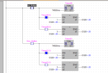
It looks like if the button is pressed, then it adds 1 to the speed, if button held it add 3 same for decrement. so if the button is pressed once for say half a second it increments by 1, if held in it increments by 3 but depending on scan time will increment by either 1 or 3 every scan.
 
I just re-created the logic, assume the button is on while pressed, then if pressed for les than 0.5 seconds then it will increment by 1 x scan rate.
If held for more than 0.5 secs it will increment at 3 x scan rate.
The only thing we do not know is what is T19 doing.
below is also a simpler version of the logic minus all the **** but done in FBD as it's quicker.

Inc_Dec1.png
 
It is a reciprocating timer of 400ms (standard timers are of 100ms increments so K4 is 400ms, that makes sense, it is used as a pulse to increment the value rather than as I stated use the scan time. not sure why they had the T20/21 as low as K5 as this is only 500ms so a fine line between pushing for less than half a second & a pulse at 400ms.
They could as easily used either the 0.2s or 1 s clock bits SM411 or SM412 clock pulses & use the built in PLS function on contacts.
 
To answer some of your questions, drbitboy, yes PB is pushbutton. The operator makes some selections via clicks on the HMI and there's also a physical console with buttons to be pressed by finger.
 
It's very poorly written, for example when the operator pushes the button say for a short time it may be that the time the push button is on is during T19 timing so it will not increment or decrement the value, holding it for more than 0.5 seconds will increment at 3 per pulse from T19, what the programmer has tried to do is on a wing & a prayer, for small increments the operator has to press the button for less than 0.5 seconds but 0.4 seconds to increment by 1.
It would have been better to use the button as a pulse for the increment by 1, this is important as if there is a button on the HMI that does the same job depending on the update i.e. coms, the button may not send a "1" to the PLC, on the other hand if a lot of data is being read/written it probably more often than not miss the increment.
Assume two buttons (one HMI & one hard wired) the hard wired one will update every scan so assume a scan rate of 50ms then it is pretty instant, however, pressing a button on the HMI could take more than the 400ms required to update, this will depend on the coms load & type of interface i.e. 232/Ethernet.
see attached code:

Inc_Dec.png
 

Similar Topics

Hi One of the PLC's that I maintain/update is a Mitsubishi Q-Series, probably installed about 10 years ago. At the moment, ALL the wires from...
Replies
13
Views
1,172
As per title, looking at how to scale an input, 4-20mA to a real value. Taking it in as an integer (RAW data)and converting it to a real, being...
Replies
0
Views
2,028
Hi all, weve just moved over to Mitsubishi GX IEC Developer 6.01 with the Q-Series PLC, used to have Allen Bradley SLC 500 Series & RS Logix, my...
Replies
4
Views
3,407
hi! i started to use the gx iec developer two years ago (now using ver. 6.01). about 6 months ago i started to programm q-series plc´s (mitsu)...
Replies
0
Views
4,220
hi! i started to use the gx iec developer two years ago (now using ver. 6.01). about 6 months ago i started to programm q-series plc´s (mitsu)...
Replies
0
Views
7,525
Back
Top Bottom