![]() ![]() ![]() ![]() ![]() ![]() |
||
![]() |
||
![]() ![]() ![]() ![]() This board is for PLC Related Q&A ONLY. Please DON'T use it for advertising, etc. |
||
![]() |
![]() |
#1 |
Member
|
Module Defined Data Type in RSLogix 5000
Hello,
This is not a question that's causing me problems, but I'm uncomfortable not understanding it: In RSLogix 5000, I have a module-defined data type for an Ethernet/IP commanded stepper. When I open the MDDT, Logix tells me that it is 20 bytes. However, I'm seeing 24 bytes in the member list. What gives? Here's the structure Code:
COMMAND_WORD_0, INT, Binary Bit_1, BOOL, Decimal . . . Bit_16, BOOL, Decimal COMMAND_WORD_1, INT, Binary Bit_17, BOOL, Decimal . . . Bit_32, BOOL, Decimal POSITION, DINT, Decimal SPEED, DINT, Decimal ACCEL, INT, Decimal DECEL, INT, Decimal CURRENT, INT, Decimal JERK, INT, Decimal Now, looking at the manual, I see that the BOOLs actually correspond to the individual bits of the COMMAND_WORDs that precede them, and obviously RSLogix recognizes this. My question is, why isn't RSLogix counting those BOOLs? Does it have to do with something in the EDS file? When I try to replicate this structure with a UDT, the BOOLs get counted. Thanks. |
![]() |
![]() |
#2 |
Lifetime Supporting Member + Moderator
|
I only count 20 bytes in your list:
2 bytes COMMAND_WORD_0 2 bytes COMMAND_WORD_1 4 bytes POSITION, DINT 4 bytes SPEED, DINT 2 bytes ACCEL, INT 2 bytes DECEL, INT 2 bytes CURRENT, INT 2 bytes JERK, INT The BOOLS are overlays of the Command Word 0 and Command Word 1 integers, so they do not get their own memory space. Am I just adding incorrectly ? I've had only one cup of coffee this morning. |
![]() |
![]() |
#3 |
Member
|
The following Rockwell Technote discusses UDT memory allocation:
RSLogix 5000 User Defined data types (UDT) (TechConnect Required) In it, there is reference to members "hidden from the user" in the situation where boolean elements are encapsulated by a larger integer (i.e., SINT, INT, or DINT). It may be possible this is what is happening with the COMMAND_WORD_ integers in this module defined type. This is a just a guess, but if examined in the L5K file it might appear as implied by the technote: data type xxx_UDT (FamilyType := NoFamily) .... INT COMMAND_WORD_0 (Hidden := 1); BIT Bit_1 : 0; BIT Bit_2 : 1; ... BIT Bit_16 : 15; INT COMMAND_WORD_1 (Hidden := 1); BIT Bit_17 : 0; ... END_DATATYPE I'd be curious if this is what you find. |
![]() |
![]() |
#4 | |
Member
|
Quote:
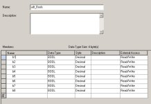
For what it's worth, I did find the attached UDT yields the following datatype in the L5K: DATATYPE udt_Bools (FamilyType := NoFamily) SINT ZZZZZZZZZZudt_Bools0 (Hidden := 1); BIT b1 ZZZZZZZZZZudt_Bools0 : 0; BIT b2 ZZZZZZZZZZudt_Bools0 : 1; BIT b3 ZZZZZZZZZZudt_Bools0 : 2; BIT b4 ZZZZZZZZZZudt_Bools0 : 3; BIT b5 ZZZZZZZZZZudt_Bools0 : 4; BIT b6 ZZZZZZZZZZudt_Bools0 : 5; BIT b7 ZZZZZZZZZZudt_Bools0 : 6; BIT b8 ZZZZZZZZZZudt_Bools0 : 7; END_DATATYPE |
|
![]() |
![]() |
#5 | |
Member
|
Quote:
I guess what I'm really trying to find out is whether this is a capability that we have in UDT creation, or is it something that can only be done with Module-Defined Data Types. As I said, when I tried to replicate this exact structure in a UDT, it calculated 24 bytes, since it assigned the BOOLs to their own memory space. Thanks. |
|
![]() |
![]() |
#6 | |
Member
|
Ken gave me the terminology that I was looking for to do a meaningful search.
From the Knowledgebase: Quote:
|
|
![]() |
![]() |
#7 |
Member
|
Using the template from the Tech Note, I was able to create my own data type in the L5K file with bit overlays:
Code:
DATATYPE SMD23E2_Status (FamilyType := NoFamily) SINT SMD23E2_Status0 (Hidden := 1); BIT ConnectionFaulted SMD23E2_Status0 : 0 (Radix := Binary); INT STATUS_WORD_0 (Radix := Binary); BIT Moving_CW STATUS_WORD_0 : 0 (Radix := Binary); BIT Moving_CCW STATUS_WORD_0 : 1 (Radix := Binary); BIT In_Hold_State STATUS_WORD_0 : 2 (Radix := Binary); BIT Stopped STATUS_WORD_0 : 3 (Radix := Binary); BIT At_Home STATUS_WORD_0 : 4 (Radix := Binary); BIT Accelerating STATUS_WORD_0 : 5 (Radix := Binary); BIT Decelerating STATUS_WORD_0 : 6 (Radix := Binary); BIT Move_Complete STATUS_WORD_0 : 7 (Radix := Binary); BIT In_Assembled_Mode STATUS_WORD_0 : 8 (Radix := Binary); BIT Wait_For_Assembled_Segment STATUS_WORD_0 : 9 (Radix := Binary); BIT Position_Invalid STATUS_WORD_0 : 10 (Radix := Binary); BIT Input_Error STATUS_WORD_0 : 11 (Radix := Binary); BIT Command_Error STATUS_WORD_0 : 12 (Radix := Binary); BIT Configuration_Error STATUS_WORD_0 : 13 (Radix := Binary); BIT Module_OK STATUS_WORD_0 : 14 (Radix := Binary); BIT Mode_Flag STATUS_WORD_0 : 15 (Radix := Binary); INT STATUS_WORD_1 (Radix := Binary); BIT IN1_active STATUS_WORD_1 : 0 (Radix := Binary); BIT IN2_active STATUS_WORD_1 : 1 (Radix := Binary); BIT Temperature_Above_90C STATUS_WORD_1 : 2 (Radix := Binary); BIT PLC_in_PROG_Mode STATUS_WORD_1 : 3 (Radix := Binary); BIT Connection_Was_Lost STATUS_WORD_1 : 4 (Radix := Binary); BIT Driver_Fault STATUS_WORD_1 : 5 (Radix := Binary); BIT Invalid_Jog_Change STATUS_WORD_1 : 6 (Radix := Binary); BIT Limit_Condition STATUS_WORD_1 : 7 (Radix := Binary); BIT Heartbeat_Bit STATUS_WORD_1 : 8 (Radix := Binary); BIT Multi_turn_Encoder_Error STATUS_WORD_1 : 9 (Radix := Binary); BIT Acknowledge_Flag STATUS_WORD_1 : 10 (Radix := Binary); BIT Stall_Detected STATUS_WORD_1 : 11 (Radix := Binary); BIT Drive_Is_Enabled STATUS_WORD_1 : 12 (Radix := Binary); DINT MOTOR_POSITION; DINT ENCODER_POSITION; DINT TRAPPED_ENCODER_POSITION; INT PROGRAMMED_MOTOR_CURRENT; INT JERK_STATUS; END_DATATYPE |
![]() |
![]() |
#8 |
Lifetime Supporting Member
![]() ![]() Join Date: Jun 2013
Location: Texas
Posts: 15
|
If you want to know the exact size and layout of a module-defined datatype, open, close and reopen your ACD file in RSLogix 5000, then search in the Windows user's TEMP folder for an XML file named TagInfo. This file is temporary, so don't close RSLogix yet. If you are familiar with the L5X file format, the contents of this file will be easy to understand and will take the guesswork out of figuring out where the padding bytes and unused bits are. You could use this information to verify that your UDT was created correctly.
Last edited by Nomographer; January 23rd, 2018 at 09:34 PM. Reason: added last sentence |
![]() |
![]() |
#9 |
Lifetime Supporting Member
![]() ![]() Join Date: Jun 2013
Location: Texas
Posts: 15
|
There, I fixed it. Corrections in bold.
Code:
DATATYPE SMD23E2_Status (FamilyType := NoFamily) DINT SMD23E2_Status0 (Hidden := 1); BIT ConnectionFaulted SMD23E2_Status0 : 1 (Radix := Binary); INT STATUS_WORD_0 (Radix := Binary); BIT Moving_CW STATUS_WORD_0 : 0 (Radix := Binary); BIT Moving_CCW STATUS_WORD_0 : 1 (Radix := Binary); BIT In_Hold_State STATUS_WORD_0 : 2 (Radix := Binary); BIT Stopped STATUS_WORD_0 : 3 (Radix := Binary); BIT At_Home STATUS_WORD_0 : 4 (Radix := Binary); BIT Accelerating STATUS_WORD_0 : 5 (Radix := Binary); BIT Decelerating STATUS_WORD_0 : 6 (Radix := Binary); BIT Move_Complete STATUS_WORD_0 : 7 (Radix := Binary); BIT In_Assembled_Mode STATUS_WORD_0 : 8 (Radix := Binary); BIT Wait_For_Assembled_Segment STATUS_WORD_0 : 9 (Radix := Binary); BIT Position_Invalid STATUS_WORD_0 : 10 (Radix := Binary); BIT Input_Error STATUS_WORD_0 : 11 (Radix := Binary); BIT Command_Error STATUS_WORD_0 : 12 (Radix := Binary); BIT Configuration_Error STATUS_WORD_0 : 13 (Radix := Binary); BIT Module_OK STATUS_WORD_0 : 14 (Radix := Binary); BIT Mode_Flag STATUS_WORD_0 : 15 (Radix := Binary); INT STATUS_WORD_1 (Radix := Binary); BIT IN1_active STATUS_WORD_1 : 0 (Radix := Binary); BIT IN2_active STATUS_WORD_1 : 1 (Radix := Binary); BIT Temperature_Above_90C STATUS_WORD_1 : 4 (Radix := Binary); BIT PLC_in_PROG_Mode STATUS_WORD_1 : 5 (Radix := Binary); BIT Connection_Was_Lost STATUS_WORD_1 : 6 (Radix := Binary); BIT Driver_Fault STATUS_WORD_1 : 7 (Radix := Binary); BIT Invalid_Jog_Change STATUS_WORD_1 : 9 (Radix := Binary); BIT Limit_Condition STATUS_WORD_1 : 10 (Radix := Binary); BIT Heartbeat_Bit STATUS_WORD_1 : 11 (Radix := Binary); BIT Multi_turn_Encoder_Error STATUS_WORD_1 : 12 (Radix := Binary); BIT Acknowledge_Flag STATUS_WORD_1 : 13 (Radix := Binary); BIT Stall_Detected STATUS_WORD_1 : 14 (Radix := Binary); BIT Drive_Is_Enabled STATUS_WORD_1 : 15 (Radix := Binary); DINT MOTOR_POSITION; DINT ENCODER_POSITION; DINT TRAPPED_ENCODER_POSITION; INT PROGRAMMED_MOTOR_CURRENT; INT JERK_STATUS; END_DATATYPE |
![]() |
![]() |
Bookmarks |
Currently Active Users Viewing This Thread: 1 (0 members and 1 guests) | |
Thread Tools | |
Display Modes | |
|
|
![]() |
||||
Thread | Thread Starter | Forum | Replies | Last Post |
MicroLogix 1400 RTD Module | Jason Ozolins | LIVE PLC Questions And Answers | 8 | June 14th, 2016 03:12 PM |
Logix 5000 install problem | smiller | LIVE PLC Questions And Answers | 16 | May 26th, 2015 10:47 PM |
Rslogix 5000 data type INT change sign | Ivann | LIVE PLC Questions And Answers | 3 | May 24th, 2013 11:32 AM |
Logix 5000 Module Defined | bobwithdana | LIVE PLC Questions And Answers | 1 | March 19th, 2009 06:08 PM |
RSLogix 5000: More than one Generic Ethernet Module To The Same IP Address | broadleaf111 | LIVE PLC Questions And Answers | 8 | March 29th, 2008 08:25 AM |