Output signal is high when bit was low... Siemens S7 200

AutomationTechBrian

Lifetime Supporting Member
Join Date
Jul 2013
Location
St. Cloud, MN
Posts
669
I don't know what to think about this...

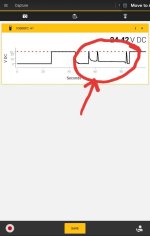
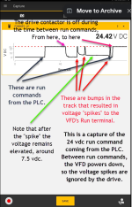
When a "finger car" travels over a bump, there is a spike in the output Q1.3 (24 vdc output). I've captured it with a Fluke trending app. (see pic) The output should not have the spikes in between the longer 24 v sections. In addition, instead of going back to 0, it hovers around 7 vdc for a while.

This output is for a run command on a VFD. I can defeat the false run commands by programming a permissive on another VFD terminal. But I'm concerned about the possibility that the PLC output is going bad. The I/O is not separate from the CPU, and this is an obsolete PLC.

Do you guys have any thoughts on this? Should we be worried about the PLC failing? Have you experienced this?

Fingercar.jpg Panel.jpg FlukeTrend.jpg
 
Looking at the work you put into this, you might have gone true these steps already, but I will mention them anyway, this is the lazy approach :)

First I would check there is a "Prell" routine on the input to your routine and add a counter on your output coil, just to make sure everything is working great in that end.

Then I would setup a second output, energized from the same routine paralle to the first output and measure the output voltage on this one, if this one one is OK, then I would look at the wirering to the VFD or the VFD it self.

If you are measuring the same spikes on the second output, I would move it to a different output card, just to check if its a hardware issue in the PLC.
 
I would check what is said above first because, i would be surprise if the plc hardwire make the contact to close by itself from time to time. It is more likely a program glitch or a parasit voltage coming from the to the vfd itself. especially if you are using the relay version, there is small relay soldered on the plc board. And a relay contact will more likely not close or stuck close if too much power has traveled into it....

Another thing i have seen quite few times is a bad return junction. a loose connection for your 24vdc- could make this kind of things. If the fluke is on a solid return but your tested circuit miss it s return from time to time, you may see a residual voltage...
 
Here's one detail I left out... the vfd is actually powered down during the spikes. A contactor powers up the drive a few seconds before the Run output is closed. When I put a new drive in, I'll change that to keep the drive powered, but use a run enable instead. You've given me some good ideas to try the next time I'm there.
 
Try adding a load to the PLC output. A small relay to pull down any leakage.

I had a project where a TRIAC output controlled an AC adapter to a laser. The leakage current was enough to build up a charge in the AC adapter and cause the laser to flash about every 3/4 seconds.
 
I'm mulling over some of the things I saw yesterday that are associated with the drive, and I'm starting to see a story unfold of issues they had converting the contactors to VFDs. There were things that didn't make sense at the time. For instance:

1. The "VFD Run" output has a duplicate output. I was watching the output trend graph in MicroWIN and noticed there is another VFD output that has the exact same behavior.

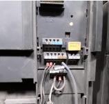
2. There is a resistor on the VFD terminals from control ground to input 3. (see pic) Input 3 has no function assigned to it.

3. They use a Siemens contactor to power down the drive when the other axis is running. That seemed a little extreme to me at first, ...and a little hard on the drive. They told me it used to be powered by contactors, so at first I assumed it was a hold-over from that era. This drive must cycle power 100-200 times a day! The drive is a Micromaster 420.

These things are starting to make sense now.

So right now, they have a two-step process for the VFD to run. First, output Q1.7 energizes the contactor, which powers the drive. Then Q1.3 energizes for the Run command. Reverse needs both Q1.3 and Q1.4.

I started looking at the fingercar because it was getting an overvoltage fault whenever it would hit a bump (in Run) while carrying a full load. At first I suspected it was losing the run command from the PLC, and the stopping at full speed with a full load was creating the overvoltage from the motor regen. After testing and chatting with my Siemens distributor drive tech, it seems the problem could be basically an old VFD flaking out. I was getting ready to replace the drive, and was going through control details for installing a new drive, which would be powered all the time. I was curious why the drive would power down between use and decided to watch a trend of the output. That's when I saw the spikes.

Since this is not a network-connected drive, I think I'll use one of the new Yaskawa GA800 drives and program a delay on a "drive enable" (using Drive Wizard) to keep the output spikes from lining up on both the Run and Enable outputs, ...if that's what is happening. I'm still curious if there is a PLC issue brewing. I'm just getting into the Siemens world, but I know the S7 200 is obsolete.

Terminals.png
 
Follow-up....

I just realized what was causing the overvoltage. It's not from losing the run command. My guess is that when the fingercar goes over a bump, a voltage spike happens in the control wires for the FWD/REV terminal. The drive is trying to change directions while in run! That makes sense because it only happens in FWD.

I was looking at this pic when it came to me:

Fingercar Run Command Spikes.png
 
I have worked on one similar to this in a brick plant, first call was that the 24v power supply capacitors were shot & the 24v was more like a sinewave, however, I do not think that is your problem. The next call I had to this was the multicore lead to the finger car, as this reels out and in one of the 24v feed cables had broke internally and as the finger car moved from the main carriage the cable would make/break the wires in the cable, as the cable was a special multicore with a combination of 3 ph, 24v DC & signal cables a temporary fix was to wire a small silflex type cable tied to the main cable, not ideal but it got them away until another cable was delivered.
If this signal is derived from the main panel via the cable reel then it's a good bet this is the problem.
 
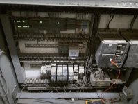
From that picture alone, it look a bloody mess. It's been maintenance-manned at some point over the years.

If time and budget allows, lance the boil and re-do it the whole thing.
 

Similar Topics

I have a customer that wants to use a single MicroMotion flow meter output (24VDC high speed digital) to go to various batch controllers (pulse...
Replies
8
Views
2,731
Hello Friends, I am looking for a way to take my PID Output( it is the result of my PI Algorithm in Real format) and generate a PWM Signal in...
Replies
16
Views
2,510
i have a question, is there a way to convert 6 outputs of ge fanuc to a number on lcd tb screen by usb or hdmi? so for example if Q34 becomes...
Replies
3
Views
1,215
Good day guys, am new here Am using a 1765-Of8 analog output card to sent 0-5v signal for a remote setpoint to a temperature controller of 1-5v...
Replies
2
Views
1,715
I know of and have used the pot to analog signal condtioners. I am looking for the opposite. I need to convert a 0-5V (or 0-10V, or 4-20MA) to...
Replies
10
Views
2,821
Back
Top Bottom