Need help getting and average value

sparkytex

Lifetime Supporting Member
Join Date
Jun 2013
Location
Port Hardy B.C.
Posts
354
Hello all,

here's what I'm trying to do. we have evaporators that evaporate the water from the liquor created from digesting pulp. There's 8 evaporators altogether working from 8 (start of the line where the liquor is pumped into) ending in 1. #8 has the most vacuum and the liquor is the thinnest at this stage as there's lots of water in it. We just installed a new motor with a VFD to work with a PID control to control pressure in the header to the evaps so there's a constant pressure which insures constant flow of liquor. I have this tuned and it works great holding its set point in auto at 40 PSI.

However we discovered that #8 body level transmitter isn't quite the best style of transmitter for the application. The body levels work off their own PID control with level and a control valve, I.E. level high close valve that controls liquor flow to the body and vice versa. This loop has been all over the place for years and no one has been able to tune it. I found out with a trend that if I put the PID into manual with 30% open on the valve the level in the sight glass on the body does not move at all (perfect level control with 40 PSI header pressure) however the level transmitter is still bouncing around like crazy saying its dropping 15% level in a matter of seconds. This is obviously inaccurate as I can see the level is perfect through the sight glass. No wonder why this cant be tuned properly because the PID is always chasing a false reading.

What I was thinking of doing was created an average of the Process variable (level in #8) and using that as the new process variable for the PID control so its not bouncing all over the place trying to satisfy a constant fluctuating false reading. I'm using RSLogix 5 on a PLC 5 and I remember you can use an FAL instruction to get averages. Can someone guide me through this or suggest an alternate way to get an running average of about 30 seconds from the level transmitter.

thanks, TEX
 
Personally, I would attack the problem with the level transmitter fluctuating first - make certain grounding is proper and cabling dressed well away from noise sources.
 
Personally, I would attack the problem with the level transmitter fluctuating first - make certain grounding is proper and cabling dressed well away from noise sources.

Yes the instrument mechanic is working on it right now, its just the issue that its a real hard level to get an accurate readout as there is a lot of vacuum in the vessel as well as the liquor itself foams up quite a bit which can lead to inaccurate readings as well. My thought with a running average was the PID would have a smoother readout to work with. That being said even if I don't decide to use the running average I'd still like to know how to make one for future use in other applications!!
 
If your instrument mechanic does not find a problem then a filter might be
a solution for you. See text.

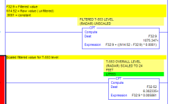
FV=FV+C(NV-FV)
Where:
FV= Filtered value
C= constant (range 0-.99) The smaller the number the more dampening.
NV= New Value
 
If your instrument mechanic does not find a problem then a filter might be
a solution for you. See text.

FV=FV+C(NV-FV)
Where:
FV= Filtered value
C= constant (range 0-.99) The smaller the number the more dampening.
NV= New Value

I'm find that confusing as I've had zero experience programming a filter or an averaged value. Is there any way you could give me an example of both in Ladder logic for RSLogix 5 If its not too much to ask? I'd be very grateful!
 
You could use the FAL in INC Mode to populate The Array of Registers with Values when condition true. Then use Brute force method to Average.
Make a new routine
Rung 0 MOV 0 N7:10 or CLR N7:10
Rung 1__ADD Source A N7:0 Source B N7:10 Destination N7:10
Rung 2__ADD Source A N7:1 Source B N7:10 Destination N7:10
Rung 3__ADD Source A N7:2 Source B N7:10 Destination N7:10
Rung 4__ADD Source A N7:3 Source B N7:10 Destination N7:10
Rung 5__ADD Source A N7:4 Source B N7:10 Destination N7:10
Rung 6__ADD Source A N7:5 Source B N7:10 Destination N7:10
Rung 7__ADD Source A N7:6 Source B N7:10 Destination N7:10
Rung 8__ADD Source A N7:7 Source B N7:10 Destination N7:10
Rung 9__ADD Source A N7:8 Source B N7:10 Destination N7:10
Rung 10_ADD Source A N7:9 Source B N7:10 Destination N7:10
Rung 11_DIV Source A N7:10 Source B 10 Destination N7:11

Of course the first 30 seconds will not be correct until FAL is Full of Values.
 
what type of sight glass do you have?
a tube or a windiw in the tank?
a tube will not give you realtime view of the tank.

also, check your wiring.
is the transmitter cable shielded?
is this 0-10 volts or 4-20?
make sure only one end of the shielded cable is grounded. i prefer the plc panel.

regards,
james
 
The instrument mechanic managed to solve the problem by changing out some old stainless tube and some re-calibrating. Its definitely a lot better than it was. its not jumping 15% intervals in level any more and I'm able to re-tune the PID with a proper signal from the level transmitter. The sight glass is a window style so you get a real accurate view of the level in the body. and this application is 4-20 mA not 0-10v.

Mickey, excuse my greenness on the subject, I have no one here to teach me and all the experience I have is the hours and hours of reading and trial and error in the field. I switched over from being a sparky to automation and process control and was supposed to be trained to take over by the fellow who has been here for 20 years and was about to retire but he ended up quitting and I had to take over with very little knowledge on PLC's because the company had no other option. It's been a struggle but I'm starting to get a grasp on things finally, but have tonnes to learn still.

having said that, what is the constant in that formula you have in the CPT function. you have it as .0001.

I've never been formally taught how to use FAL or the FIFO instruction, only experience I have is with existing logic and troubleshooting on them. I have never programmed either instructions.
 
what is the constant in that formula you have in the CPT function

The formula is taking the difference between the new raw value and the old filtered value. Then taking a portion of that difference by multipling the difference by the constant. Then adding that to the new filtered value.

The constant in that snap shot would be a very heavily filtered value. That is a very old program and I dought that value of .0001 is what ended up in the running program.
A value of .05 to .1 might be a more realistic value.

The best way to do it is to use a floating point register for the constant so it can be adjusted on the fly. Then create a trend to monitor the result of the filter as you change the constant's value.
 
Last edited:
Mickey's solution seem the best one for a filter but i use one maybe easier to understand, i just do like a standard averaging: ADD each scan, the moving value to another float and i count number of scan elapsed with another ADD instruction in another float. After an ajustable scan count reached, i just divide the accumulated value by number of scan elapsed to get the averaged value and reset both float to 0 and let it start again.

this solution work good with just a little bit of filtering, if you want to filter few seconds, you would better use FV=FV+C(NV-FV)

For the capacitor across the input terminal!!!It would work but in industrial environnement IMO, this isn't a safe solution. Imagine the reading stop during night shift and someone try to figure it out and come across the stange round thing connected to the terminals...Or someone else replace the card or the small solid wire from the cap get loose among the multistand copper wire connected beside it...
 
Last edited:
Mickey is right on target. If you google search 'First Order Lag Filter', there is a great explanation by steidl at execpc.com. I just implemented one of these filters this week and it worked great: a nice selectable low-pass filter
 

Similar Topics

Hey guys, I'm at a waste water treatment plant trying to get their UV system running. I've traced the problem down to a AOI that's causing the...
Replies
8
Views
2,676
Hello, Could someone PLEASE have a look at these files and convert them to a pdf for me? Thank you
Replies
2
Views
2,250
I've been tinkering with PLC's for a few years now, I need a little help figuring out what extra software I need for some projects I'll be working...
Replies
7
Views
2,307
I have a new project that I have started where the customer has me using an Ultra 3000 servo drive, 2098-DSD-005 I believe is the part# with a TL...
Replies
2
Views
2,891
I'm fairly new to Rockwell software, I've had some basic training in the past but nothing too advanced. My company and I use Reliable products for...
Replies
11
Views
340
Back
Top Bottom