Modbus RTU Master RS485 Voltmeter

Norberto68

Member
Join Date
Jun 2017
Location
Mexico
Posts
7
Hi to everyone.

I have to connect a Voltmeter that uses the RS845 comm protocol to a PLC Allen Bradley Micrologix 1100 and read the voltmeter values.

There are only two cables named A and B in the voltmeter. The ML 1100 is suposed to support RS485 but I dont know how to connect the cables of the voltmeter and how to read the values.

Voltmeter Info

-9600 bauds
-ID 20
-Parity None
-8 bits data
-1 bits stop
 
Last edited:
Get a 1763-NC01 to break out the CH0 pins for RS-485. You could do it without this handy little piece, but it is $40 well spent in my opinion.

Set the Channel configuration to RS-485 No Handshaking in order to enable the port to use RS485 pins rather than the RS-232 pins. Set the Protocol to Modbus Master.

Write MSG control logic and instructions to read the data from the meter. You'll have to use its manual to determine the addresses and function codes it supports.

See this link for pinout:
http://www.plctalk.net/qanda/showpost.php?p=528573&postcount=6

I see 3 pins in the right side of that diagram

An A, a B and a COMM but I only have two wires A and B in my voltmeter. Is it necessary to have a common? Im so lost, I configured everything but I keep receiving nothing. I connected the wires directly to A and B to pins 1 and 8. Is it bad?
 
I see 3 pins in the right side of that diagram

An A, a B and a COMM but I only have two wires A and B in my voltmeter. Is it necessary to have a common? Im so lost, I configured everything but I keep receiving nothing. I connected the wires directly to A and B to pins 1 and 8. Is it bad?

Noberto68

You said you connected wires A and B to pins 1 and 8. Pins 1 and 8 according to this pinout diagram are both signal pins. One wire should be used as a signal input and the other should be ground or return. Try wiring wires A and B to pins 1 and 2 or 2 and 8.
 
Noberto68

You said you connected wires A and B to pins 1 and 8. Pins 1 and 8 according to this pinout diagram are both signal pins. One wire should be used as a signal input and the other should be ground or return. Try wiring wires A and B to pins 1 and 2 or 2 and 8.

I tried connecting A and B in 1 and 2, send the MSG.
Then reverse the cables, send the MSG.
Connecting A and B in 2 and 8 send the MSG.
Then reverse the cables, send the MSG.

Every time I did that I received Message timed out.

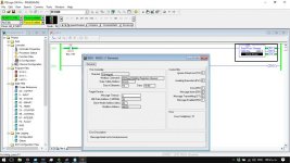
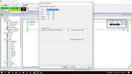
This is my configuration.

TSHOOTMSG.jpgTSHOOTMSG2.jpg
 
The sales website suggests that the default data rate for the voltmeter is only 2400 baud.

Are you sure it's set for 9600 baud and Slave ID 20 (the default slave ID is 1).

I think that Tshooot45 is incorrect on his advice regarding the pinout;

If your slave device is has no Signal Common for the RS-485 port, then connect the MicroLogix signal common (Pin 2) to the voltmeter's Ground or Chassis connection.

Pins 1 and 8 are the RS485 signal pins on the MicroLogix 1100 controller port.

While it was nice of Kittydog42 to post a pinout, it's confusing because it references a "cable side" and uses color codes that are specific to a cable he doesn't specify or define.

If you don't have the 1763-NC01 cable, then be sure to carefully ring out the pins and wires with a meter.
 
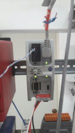
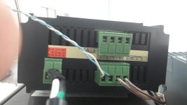
This is what I have... With the Advanced converter I conect the Voltmeter A and B to the RS485 port and the 232 port to Allen Bradley. The TX in the converter flashes When I send the MSG from PLC but I receive NOTHING from Voltmeter :cry:

01.jpg

03.jpg

04.jpg

05.jpg

06.jpg
 
Thanks very much for the photos !

The 1761-NET-AIC device makes things a little easier.

In the MicroLogix configuration, don't set up the serial port for "485 Network-No Handshaking". That is a setting for when you are connected *directly* to the MicroLogix port on pins 1 and 8.

Instead, set it for "No Handshaking".

The 1761-NET-AIC data pins are labeled A and B. You will of course want to try swapping them, because no two manufacturers label the data pins the same way.

The 1761-NET-AIC has a dedicated Data Common pin, labeled "COM". This should be connected to something on the voltmeter that fulfills the function of the communication system common or ground. Maybe terminal "70" labeled "COM", if those are DC discrete inputs on the other connector.

Another good way to test this system would be to plug in a PC to the 1761-NET-AIC and use a Modbus RTU testing program (I like Chipkin Automation's Modbus Scanner tool) to test your serial settings and addressing.
 
That COMM terminal does not exists in this model... Before I proceed to connect the 8 Pin cable i changed to No handshaking to activate 232 protocol pins (Correct me if wrong) I searched all the web but i cant find something useful.
 
Do you have a link for the manual? I looked at the page that you pointed us to and it doesn't have a link to the manual (that I saw).

Searching for the meter in google returned other 485 meters, but not yours.

Looking through one of the other cut sheets, it listed the RS485 link as a one way transmission. Could it be that your meter needs to be the master?
 
Before I proceed to connect the 8 Pin cable i changed to No handshaking to activate 232 protocol pins (Correct me if wrong)

That was correct.

RS-485 networking always requires that the devices have a common voltage reference.

Many systems (like A-B) choose to use a dedicated wire in the network for that purpose. Many other systems choose a cheaper route of using the chassis ground or even earth ground as a reference point.

You must find some kind of DC common connector on that meter. It's simply impossible for it to work without one.
 

Similar Topics

Hi Guys, I am a new member and this is my first post! I have a little PLC experience but it is mostly with siemens logo and using ladder...
Replies
4
Views
902
Currently I'm working in a project, and there is a problem, we need to show what is going on with the CR30 through an app developed in VB.NET, we...
Replies
2
Views
609
Hello all, I am trying to setup my MicroLogix 1100 as a modbus RTU master for a modbus network containing multiple modbus RTU slaves. I currently...
Replies
7
Views
3,924
I successfully got a Micro 820 (Slave) and Red Lion HMI (Master) to work together using Modbus TCP. But now I need to add an Automation Direct...
Replies
3
Views
2,656
Hello, I am using the Micro830 (2080-LC30-24QWB) with the 2080-SERIALISOL in slot 1. I am having an issue setting up the Micro830 to communicate...
Replies
5
Views
3,202
Back
Top Bottom