PLC-5 1771 ASB module ACTIVE light blinking

mylespetro

Member
Join Date
Dec 2015
Location
NS
Posts
740
Hey everyone,


Trying to bench test the I/O on a program that I converted from a PLC-5 processor to a ControlLogix processor but still using the PLC-5 I/O as remote I/O and I'm running into an issue that's left me scratching my head. Currently there are 5 RIO racks (0, 2 3 4 5 - rack 1 exists physically but with no cards in it), but when I set the ASB module to rack 0, the ACTIVE light on the module blinks, indicating that the remote adapter (CLX processor I believe) is not actively controlling I/O. When I switch the ASB module to be any other rack, there are no issues, only when I'm on rack 0. The real rack and my test rack are both full racks (8 I/O groups), and I've tried deleting and recreating the rack in the RIO setup in my CLX program, as well as verifying the chassis and ASB module dip switches, but I can't seem to figure it out. As a side note, I can see inputs change when I'm testing rack 0, but I can't make outputs come on, which is what I assumed it means by "Remote adapter not actively controlling I/O," that it will still scan inputs but will not set outputs.


If I go to the ASB properties for rack 0 under my DHRIO card, it says Status: Running, and Adapter Faulted: No, but the DHRIO module status itself says Minor Fault: Recoverable. Not sure if that gives any clues, but just something I noticed.
 
Another note, we are using single slot addressing for all racks. Chassis switches are set for single slot addressing as well.
 
Last edited:
What is the size of the chassis? Could there be a conflict with Logical Rack 1? Check how the scanner module rack sizes are configured.

The physical chassis itself is a 16-slot chassis, I have all racks set as full racks in the rack config.
 
So with single slot addressing, a full logical rack starting at slot 0 would be 8 slots, and the next 8 slots would automatically be assigned as logical rack 1.

That seems to conflict with a separate ASB module also configured to start as logical rack 1.

It has been many years since I dealt with PLC-5 RIO setup and have never done it with a Logix 5000 master, so some of my statement here is speculation.
 
As far as I can tell, I have to have it set to a full rack, it won't physically let me change it to anything else because I have 7 (technically 6, the in-chassis power supply is in slot 0) cards, and that's the largest rack size available. Just realized the rack in the panel is actually a 12-slot, with rack 0 taking up the first 8 slots and rack 1 module groups 0 through 3 in the last 4 slots, but I would still think that I should have rack 0 set up as a full rack in the config.


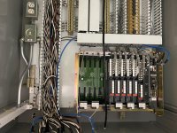
Picture of the rack is attached.


EDIT: I have no idea why the picture attached upside down

IMG_6309.jpg
 
I think it might be a processor restart lockout issue along with dip switch settings.

Your picture shows a PLC-5 instead of the ASB. I'm assuming you removed the PLC-5 and replaced it with the ASB module. Did you remember to change the chassis backplane switches when you changed to the ASB? Different switches are used for a PLC versus an adapter to determine addressing modes.

With a PLC-5 in the chassis, backplane switches 4 and 5 set the addressing mode. For one-slot addressing 4 = OFF and 5 = ON

With a 1771-ASB in the chassis, backplane switches 5 and 6 set the addressing mode. For one-slot addressing 5 = ON and 6 = OFF

With a PLC-5 in the chassis, you might have the following (example) settings:

1 = OFF turns off outputs for a hardware fault
2 = OFF Always OFF
3 = OFF Always OFF
4 = OFF 1-slot addressing
5 = ON 1-slot addressing
6 = ON no memory module transfer on powerup
7 = OFF EEPROM memory module transfer on powerup disabled
8 = OFF processor memory protection disabled

As an example, for an ASB you might have the following switch settings:

1 = OFF outputs don't hold last state for comm faults
2 = ON allow the processor to restart after a comms fault
3 = OFF Always OFF
4 = OFF Always OFF
5 = ON 1-slot addressing
6 = OFF 1-slot addressing
7 = OFF Always OFF
8 = OFF Always OFF

If you used the example for the PLC-5 as I show it (very typical), then swap in the ASB without changing the switches, you would have an invalid setting for addressing mode.

Also, switch 2 if it were in the OFF position would prevent automatic restart when communications fail. That would cause the ACTIVE light to blink if it were waiting for a manual restart. I think that there might be the issue.

OG


Thanks for the reply, switch 2 on the chassis is set to ON, to allow for processor lockout. Just for clarity, the chassis switches are as follows:


1 - OFF (Outputs de-energized on fault)

2 - ON (Processor restart enabled)

3 - OFF (Always off)

4 - OFF (Always off)

5 - ON (ON for single slot addressing)

6 - OFF (OFF for single slot addressing)

7 - OFF (Always off)

8 - OFF (Last chassis switch, set to off)


And the ASB switches are as follows for rack 0:


(SW1)
1 - ON (ON for rack #0)

2 - ON (ON for rack #0)
3 - ON (ON for rack #0)
4 - ON (ON for rack #0)
5 - ON (ON for rack #0)
6 - ON (ON for rack #0)
7 - ON (ON for first I/O group number of 0)

8 - ON (ON for first I/O group number of 0)


(SW2)
1 - ON (ON for 57.6k baud)

2 - OFF (OFF for 57.6k baud)

3 - OFF (Always off)

4 - OFF (OFF to scan all slots)


Another side note, I have done this for another system and bench tested it with no issues, but this program seems to have something different somewhere. Also to reiterate, if I change the rack number to 2 on the ASB switch and leave everything else untouched, the ACTIVE light stays solid.
 
My head keeps coming back to the PLC-5 setting to force it to start with Rack #1 instead of Rack #0, but that was a setting in the status file. It shouldn't apply here. IMO it has to come down to our hardware layout.

I'm confused how setting it to Rack #2 works, when you say you already have a rack #2. Unless you are just testing this standalone without the other chassis present. Can you clarify the test setup you are using along with what module you are using in the CLX (DHRIO or RIO).

It might be good to be clear on "racks" versus "chassis" since those are two different terms that are often used as if they are the same. I assume you mean that the "chassis containing rack #1" physically exists. In PLC-5 and RIO there is no such thing as physical racks, just physical chassis. Rack is strictly an addressing term. I can tell you get that, but for anyone else reading this, it might not be clear.

What I am getting at is I'm wondering if we are getting an issue with the rack overlap from the chassis with rack #0 and the lower half of rack #1. If there is another physical chassis with an ASB module that contains Rack #1 then we have a conflict (unless it starts with group 4). It doesn't matter if there are I/O cards or not.

OG
 
Last edited:
I will preface this by saying its been a long while ...
Some confusion - you wrote it is a 16 slot chassis with 1 slot addressing starting at rack 0.But the photo shows a 12 slot chassis with a PLC-5?


In either case - if the chassis starts at rack 0, module 0, with one slot addressing, the chassis will be two racks (16 slot - rack 0 and rack 1 or 12 slot = rack 0 and rack 1 (1/2 rack). And the 'extra' rack # will need to be in the scan list for the scanner module.
 
My head keeps coming back to the PLC-5 setting to force it to start with Rack #1 instead of Rack #0, but that was a setting in the status file. It shouldn't apply here. IMO it has to come down to our hardware layout.

I'm confused how setting it to Rack #2 works, when you say you already have a rack #2. Unless you are just testing this standalone without the other chassis present. Can you clarify the test setup you are using along with what module you are using in the CLX (DHRIO or RIO).

It might be good to be clear on "racks" versus "chassis" since those are two different terms that are often used as if they are the same. I assume you mean that the "chassis containing rack #1" physically exists. In PLC-5 and RIO there is no such thing as physical racks, just physical chassis. Rack is strictly an addressing term. I can tell you get that, but for anyone else reading this, it might not be clear.

What I am getting at is I'm wondering if we are getting an issue with the rack overlap from the chassis with rack #0 and the lower half of rack #1. If there is another physical chassis with an ASB module that contains Rack #1 then we have a conflict (unless it starts with group 4). It doesn't matter if there are I/O cards or not.

OG


Sorry for the confusion, I only have one physical chassis, which is a 16-slot. I'm changing the switches on the ASB to each individual rack when bench testing said rack. I am using a DHRIO card in the CLX chassis.


The existing hardware running the system are as follows:

CHASSIS 1 (12 slot) - this is the chassis in the picture I attached above, existing PLC-5 processor in this rack


Rack 0 - 8 slots (0-7) single slot addressing
Rack 1 - 4 slots (8-11/10-13 octal) single slot addressing, no cards whatsoever in this rack


RIO from PLC-5 processor in chassis 1 to ASB module in chassis 2


CHASSIS 2 (12 slot) - ASB module in this rack


Rack 2 - 8 slots (0-7) single slot addressing
Rack 3 (1 of 2) - 4 slots (8-11/10-13 octal) single slot addressing, also no cards in this rack - Rack 3 is configured as a full rack, continued in the next chassis

RIO paralleled from the ASB in this chassis to chassis 4


CHASSIS 3 (12 slot) - ASB module in this rack


Rack 3 (2 of 2) - 4 slots (0-3) single slot addressing
Rack 4 - 8 slots (4-11) single slot addressing


RIO from the ASB in this chassis to chassis 4


CHASSIS 4 (12 slot) - ASB module in this rack


Rack 5 - 8 slots (0-7) single slot addressing
Rack 6 - 4 slots (7-11/10-13 octal) single slot addressing


RIO paralleled from the ASB in this chassis to chassis 3


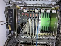
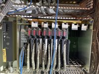
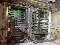
I'll attach some more pictures to this post of the racks, hopefully they upload right side up. Disregard the COMM CONTROL card in chassis 3, it used to go to a PKTX-enabled PC as a HMI, but is no longer connected.


For clarification, I'll caption each file:


IMG_6316 - Chassis 2
IMG_6212 - Chassis 3
IMG_6213 - Chassis 4
IMG_6214 - Interconnection between chassis 3 and 4. Just to show that the RIO from chassis 2 lands on 4, which is then paralleled to 3.

IMG_6316.jpg IMG_6212.jpg IMG_6213.jpg IMG_6214.jpg
 
I will preface this by saying its been a long while ...
Some confusion - you wrote it is a 16 slot chassis with 1 slot addressing starting at rack 0.But the photo shows a 12 slot chassis with a PLC-5?


In either case - if the chassis starts at rack 0, module 0, with one slot addressing, the chassis will be two racks (16 slot - rack 0 and rack 1 or 12 slot = rack 0 and rack 1 (1/2 rack). And the 'extra' rack # will need to be in the scan list for the scanner module.


Yes sorry for the confusion, the installed chassis currently running are all 12-slot, but my bench test chassis is 16-slot. I've just been testing each I/O rack individually using the first 8 slots of this bench test chassis. This has worked fine for me in the past.
 
Post a screen capture of your scan list, if the chassis is 1 slot, starting at 0, and it is either a 12 or 16 slot chassis, you have rack 1.

You don't have the problem for the other racks 2 /3 and 4/5 because all the racks in the chassis are being scanned.


Add rack 1 of the appropriate size to the scan list.
 
Last edited:
Ok, so is the PLC-5 processor in chassis 1 staying, or are you replacing it with an ASB module?

If it is staying, is that PLC-5 configured for Adapter Mode on its RIO channel? Because the Classic PLC-5 did not allow it to be used as Rack #0.

But I am assuming you are replacing it.

In your Logix software, do you have two entries for that chassis underneath the DHRIO module? The first for Rack 0 as a full rack (000 0 1). Then a second for Rack 1 as a half-rack (001 0 1/2).

Even if that rack is empty, we still need it defined so the image size of the ASB matches what the CLX has allocated. You had mentioned you had all racks configured as full racks.

OG
 
Post a screen capture of your scan list, if the chassis is 1 slot, starting at 0, and it is either a 12 or 16 slot chassis, you have rack 1.

You don't have the problem for the other racks 2 /3 and 4/5 because all the racks in the chassis are being scanned.


Add rack 1 of the appropriate size to the scan list.


I'd already tried this with the same result, I put in rack 1 as a 1/2 rack and it still gave me the ACTIVE light blinking error. At this point I'm sure it's a stupid hardware configuration thing, but I've rebuilt the racks in the scan list twice now and can't get it to work, as well as double and triple checked the DIP switches.
 

Similar Topics

A question was sent via PM this morning from a new member (Vince9521, from up in Timmins, Ontario) that I'm promoting to the main forum:
Replies
1
Views
1,075
These two RTD's are wired to channels 1 and 2 on a 1771-IR in a remote rack, communicating to a PLC-5/40 through an ASB. I believe that the RTD's...
Replies
7
Views
1,963
Hello, I am in the process of migrating a PLC-5 system over to ControlLogix and could not find any equivalent modules to convert the 1771-ALX...
Replies
2
Views
1,488
Hello, I am trying to create a network status map at a plant. I'm assuming the comm status bit of dnet nodes is in the BTR/BTW instruction that...
Replies
0
Views
979
I have a working PLC 5/10 with 1771 16 channel analog input module. Currently has 4 direct 2 wire analog signals in. Just positive and negative...
Replies
4
Views
1,623
Back
Top Bottom