PLC-5 1771 ASB module ACTIVE light blinking

Ok, so is the PLC-5 processor in chassis 1 staying, or are you replacing it with an ASB module?

If it is staying, is that PLC-5 configured for Adapter Mode on its RIO channel? Because the Classic PLC-5 did not allow it to be used as Rack #0.

But I am assuming you are replacing it.

In your Logix software, do you have two entries for that chassis underneath the DHRIO module? The first for Rack 0 as a full rack (000 0 1). Then a second for Rack 1 as a half-rack (001 0 1/2).

Even if that rack is empty, we still need it defined so the image size of the ASB matches what the CLX has allocated. You had mentioned you had all racks configured as full racks.

OG


Yes we are replacing the processor with an ASB module. I'll attach some screenshots below of the scan list in my CLX program. As I replied to Mike above, I did create rack 1 as a half rack with nothing in it, but it's still giving me the error.

RIO Scan List.PNG
 
Hey everyone, finally got around to installing this in the field, I ran into the same problem with my rack 1 and remembered to change it to a half rack and that fixed the problem. However, my rack 3 is not scanning, and I can't quite figure out how to get it talking. Every other rack is scanning, just for reference (I also had to change rack 6 to a half rack to get it to scan, but I'm not sure if that really mattered because there are no I/O cards in it).

As a reminder, my physical chassis layout is as follows, program I/O tree is above:

CHASSIS 1 (12 slot) - this is the chassis in the picture I attached above, existing PLC-5 processor in this rack


Rack 0 - 8 slots (0-7) single slot addressing
Rack 1 - 4 slots (8-11/10-13 octal) single slot addressing, no cards whatsoever in this rack


RIO from PLC-5 processor in chassis 1 to ASB module in chassis 2


CHASSIS 2 (12 slot) - ASB module in this rack


Rack 2 - 8 slots (0-7) single slot addressing
Rack 3 (1 of 2) - 4 slots (8-11/10-13 octal) single slot addressing, also no cards in this rack - Rack 3 is configured as a full rack, continued in the next chassis

RIO paralleled from the ASB in this chassis to chassis 4


CHASSIS 3 (12 slot) - ASB module in this rack


Rack 3 (2 of 2) - 4 slots (0-3) single slot addressing
Rack 4 - 8 slots (4-11) single slot addressing


RIO from the ASB in this chassis to chassis 4


CHASSIS 4 (12 slot) - ASB module in this rack


Rack 5 - 8 slots (0-7) single slot addressing
Rack 6 - 4 slots (7-11/10-13 octal) single slot addressing


RIO paralleled from the ASB in this chassis to chassis 3

I'm not sure exactly what's causing the issue, unsure if it's the fact that rack 3 begins on chassis 2 and continues on chassis 3? The ASB DIP switches on the adapter with the second half of rack 3 are assigned for rack 3, starting I/O group is 4. However, no matter how I try to configure my rack in my I/O tree it either doesn't work or won't allow me to change the I/O configuration because of an incorrect rack size or that there are modules in the module groups it's trying to eliminate. I've tried changing the rack size to 1/2 rack with a starting I/O group of 4, but it says the RIO rack size is too large for the current starting group.

The DIP switches on the ASB module with rack 3 module groups 4-7 are as follows:

SW1
1 - ON
2 - ON
3 - ON
4 - ON
5 - OFF
6 - OFF - First 6 set rack number to 3
7 - OFF
8 - ON - 7/8 set for starting I/O group of 4

SW1
1 - ON - 57.6k baud
2 - ALWAYS OFF
3 - ALWAYS OFF
4 - ALWAYS OFF

This chassis does have a 150 Ohm resistor across the RIO cable because it is physically the last chassis, so I don't think that's the issue, but I'm not positive. Any insights would be much appreciated.
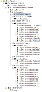
 
Figured it out, I had to delete my original rack 3 and create two separate rack 3s as 1/2 racks, one starting at I/O group 0 with no modules, and another starting at I/O group 4 with modules. I figured this out by opening the original PLC-5 program and checking the Remote I/O configuration, which showed two rack 3s as 1/2 a rack each, again, one starting at 0 and one starting at 4. Another trick that got me was that I had my I/O aliased for a full rack, i.e. O_036_Bit_07 was originally aliased to R3:O.Data[6].7 (or whatever the correct syntax is, don't have the program open in front of me), but when I created the two new rack 3s, I had them called R3_1 and R3_2, and even though R3_2 had module groups 4, 5, 6 and 7, the RIO tag it created was still an INT with [0] through [3]. Therefore, for O_036_Bit_07, it had tried to alias it to R3_2:O.Data[6].7, but I had to change it to R3_2:O.Data[2].7 to account for this offset.
 

Similar Topics

A question was sent via PM this morning from a new member (Vince9521, from up in Timmins, Ontario) that I'm promoting to the main forum:
Replies
1
Views
1,075
These two RTD's are wired to channels 1 and 2 on a 1771-IR in a remote rack, communicating to a PLC-5/40 through an ASB. I believe that the RTD's...
Replies
7
Views
1,965
Hello, I am in the process of migrating a PLC-5 system over to ControlLogix and could not find any equivalent modules to convert the 1771-ALX...
Replies
2
Views
1,489
Hello, I am trying to create a network status map at a plant. I'm assuming the comm status bit of dnet nodes is in the BTR/BTW instruction that...
Replies
0
Views
980
I have a working PLC 5/10 with 1771 16 channel analog input module. Currently has 4 direct 2 wire analog signals in. Just positive and negative...
Replies
4
Views
1,625
Back
Top Bottom