Panelbuilder32 with Devicenet, problems with designating tags

angelito0

Member
Join Date
Dec 2018
Location
Mexico
Posts
7
Good day.
I am a newbie and I need your help, I have a project but the problem is that I have never used the panelbuilder32 and I do not know how to relate the tags of the panelbuilder32 with those of the PLC, since I have seen projects where for example the activation of a pump is I: 0/0 and in panelbuilder32 it appears as I: 54/3, I have already read many manuals and nothing takes me where I want to go and I need your help.

I am using the RSLogix 5000 for a PLC 1756-L55 Contrologix5555 with Devicenet communication for a PanelView 1000 Touch.

I hope and you can help me by showing me an example or a non-AllenBradley manual because I already read them and it does not explain how to assign the tags of each object so that the panel can send the information to the PLC.

Thank you!!đź“š
 
Welcome to the PLCTalk forum community !

Unfortunately, you have chosen a relatively complicated and uncommon networking option for your first experience with an obsolete HMI terminal.

And even for popular and modern networks, asking "teach me without using the manufacturer's manuals" is a very difficult request.

If you can upload, ZIP, and post the configuration files for your system, I (and other users) can help explain how DeviceNet scanlist memory mapping and the PanelBuilder32 syntax work together in your specific system.
 
The PanelBuilder32 software considers the I/O connection from DeviceNet to be a simple flat data table named "I:w" and "O:w", where "w" is the 16-bit word offset starting at 0. You can also add a "/b" to designate a Bit inside each Word.

Those don't line up exactly with Input and Output tags in the ControlLogix for the 1756-DNB scanner, because the data from DeviceNet slaves can be "mapped" anywhere in the Input and Output array tags. The node number doesn't relate to the data location.

That alignment and "mapping" is done in the Mapping section of the 1756-DNB's Scanlist configuration in RSNetworx for DeviceNet software.

Imagine for example a 20-word Input and Output "Polled" I/O connection between the 1756-DNB and the PanelView.

That would be addressed as

I: 0 through I:19
O: 0 through O:19

in the PanelBuilder32 software itself.

But in the ControlLogix, it could be anywhere in the Slot:Input.Data[x] and Slot:Output.Data[x] array tag, depending on where the Mapping was done.

If you have both the PanelBuilder32 application and the ControlLogix application, you can probably line up those data blocks fairly easily.

If you have the PanelBuilder32 application (*.PBA) and the ControlLogix application (*.ACD) and the DeviceNet project file (*.DNT) with the Scanlist from the 1756-DNB in it, then you can determine that data alignment exactly.
 
Thank you very much for your time Ken Roach you are a very kind person, if I read the official manuals of Allen Bradley but I did not find where he explained my needs, I understand what you are talking about but in the manuals they only explain what each thing is for, if there is a different manual i would like to read it.

I have the file the files (*.PBA *.ACD and *.DNT) but still I don't know how to find any relationship since in the *.DNT it says that the mapping is from word 90 to 120, both inputs and outputs, in the HIM *.PBA it uses I:54/0 and O:54/0 and in the *.ACD it sometimes uses only a few words from the devicenet mapping :c
 
Last edited:
If you can ZIP and attach those files, folks could look at them and try to give you a direct explanation.

I was an expert on this, but it's been 10+ years since I worked on these devices together.

The 1756-DNB's I/O tags are DINT[x] arrays of 32 bits each, while I believe that the PanelView addresses the DeviceNet connection in 16 bit words.

Slot:Input.Data[90] through Slot:Input.Data[120] will be 31 DINT elements, which would be addressed in the PanelView as I:0 through I:61 and O:0 through O:61.
 
regret not being able to upload it since in the company I work for if I upload the file I could get into legal problems: '(

I understand what it tells me why that is in the manual but if they would address in PanelView as I: 0 to I: 61 and O: 0 to O: 61, likewise I do not understand how there is a relationship between assigning the start of an engine if you assign the button in HIM I: 55/0 and in Rslogix5000 it is O: 4/1.

Good example of Imagine, for example, a 20 word input and output "polled" I / O connection between the 1756-DNB and the PanelView.

That would be addressed as

I: 0 to I: 19
O: 0 to O: 19

I know that what comes in Rslogix5000 will never be the same as what is in builder32, but just as it could be:

I: 0 to I: 19 <<< The bit could fall anywhere between that range
O: 0 to O: 19

A question can I also test with Emulator 5000 for panelbuilder? maybe if I do an exercise I can understand a little more why they do not allow me to bring the panel to my house and there are scarce they are always in production u.u
 
RSLogix 5000 tags are not "O:xx". They are more like "Local:5:O.Data[x]".


If you post actual examples of actual settings in the actual programs, I can try to explain them to you.

But I am not willing to use partial examples or improper syntax.
 
OK sorry, you're right, I only did it as an example, but the correct thing is to use a good syntax, do you know where I can lean on to read some example of what I need?
 
Open your RSLogix 5000 program and look at the Input and Output tags for the 1756-DNB's slot number.

Use the actual syntax used in the actual program.
 
angelito0,

Those files, opened in their relative software, should essentially provide you with all the "reading" you should need to do here. If you are struggling with that, I would advise you, in earnest, to heed Ken's instructions carefully. You will not find better DeviceNet advice anywhere else, including any manuals you may think exist to break this down for you.

It's a bit frustrating without laying eyes on those files, isn't it Ken? Might I suggest, if you can access them, that you alternatively use the same files from this example technote to demonstrate the likely mapping in our friends application?

ID: QA1928 | Access Levels: TechConnect
PanelView Standard: ControlLogix DNB DeviceNet Example

Another possibility to be mindful of here is that the 1756-DNB scanner's relevant base Controller-Scoped Tags may be mapped/aliased to other user-defined Controller-Scoped Tags or Program-Scoped Tags. If present, that could help, or it could add a further level of complexity in identifying which "tags" in the controller are being used with the terminal.

Regards,
George


From the range that covers the HIM from 90 to 120, only this tag is the one that appears in Rslogix


Thanks for your time!
 
Last edited:
Tag names in the HMI do not necessarily share any relationship with tag names in the PLC. If the logic directly addresses the I/O rather than using aliased tags, there will not even be distinct tags.

Although you can reconstruct the I/O mapping if you know the overall I/O size and can match even a single input and output address, it's much easier if you can look at the mapping in the .DNT file.

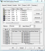
Here's an example from a machine. Look at the attached picture, which shows the mapping for a panelview named Panelview-2 in the .DNT. It is assigned as node 8, and its mapping in the PLC begins at Local:1:I.Data[6].24. It then continues for 8 words and ends with Local:1:I.Data[14].23, a total of (32*8=256) bits. The panelview uses 16-bit words, so it will have (256/16=16) words, which I can confirm by checking that the input size in its configuration is 16 (it is).

We now know where the inputs in the PLC start, and the inputs in HMI start at I:0/0. As such:
I:0/0->Local:1:I.Data[6].24
I:0/1->Local:1:I.Data[6].25
I:0/2->Local:1:I.Data[6].26
.
.
.
I:0/7->Local:1:I.Data[6].31
I:0/8->Local:1:I.Data[7].0 (Note that we reached the end of the word in the PLC; we just continue to the next word while continuing the same word in the HMI)
I:0/9->Local:1:I.Data[7].1
.
.
.
I:0/15->Local:1:I.Data[7].7
I:1/0->Local:1:I.Data[7].8 (We reach the end of the word in the HMI, but just continue on with no breaks in the PLC)
.
.
.
I:15/15->Local:1:I.Data[14].23

The .DNT mapping shows us where the data from the HMI is located; starting at the beginning of that location and at I:0/0 in the HMI we can identify the corresponding PLC location for every HMI tag.

Basically the same process for outputs.

Note that if you're using more than a single bit at a time (eg integers) BTDs will likely be used to move parts of the 32-bit PLC word into appropriately sized tags.

DNet.PNG
 
Last edited:
WOW thank you very much everything fits perfectly and I had doubts about why the BTDs were used because they are indeed being used and I am already relating one thing to the other. thousand thanks plvlce your answer filled my expectations !!
 

Similar Topics

Hello guys , im new at plc. i have a few questions hopefully someone can help me out. i extracted from an old panelview550 a pba file and...
Replies
12
Views
1,429
Hi guys I'll appreciate for your support. I want to know if there is a way to change the text of a label depending of the numeric value of a tag...
Replies
5
Views
1,083
I can't find what laptop I have our PanelBuilder32 application and license on. And Rockwell no longer supports it. Can someone please update 1...
Replies
5
Views
1,626
A tech at a remote facility had a PV550 **** out (Err 690 DH+ hardware failed). He took it out and sent it to me, and going by the label on the...
Replies
1
Views
1,256
I recently started getting "corrupted or low disk space" errors on all my backup panelbuilder32 files seemingly out of no where (been running ver...
Replies
2
Views
1,596
Back
Top Bottom