1746-NR4 RTD Module Question

ceilingwalker

Lifetime Supporting Member
Join Date
Mar 2010
Location
Phoenix, AZ
Posts
1,586
Good day all. I have an RTD module for a SLC500 5/03 that I can't get the temperature values to stop jumping from one temp to the next, on the HMI display. I don't know if there is a sampling rate or what exactly it is that I can do. The temp diplays 140-degrees F, for example, and looking at the display for only 5-seconds the temp will jump-up to 150, down to 120, then to 135, etc... . What can I do to get a more stable reading? Thank you.
 
First check for noise on your wiring. Is the cable shielded ( with shield grounded at one end) ?
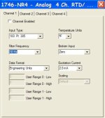
Once the above is done then you might try increasing the filter time (see picture below and manual exert.

Filter Frequency
The filter frequency field lets you select one of four filters available for a channel. The filter frequency affects the channel update time and noise rejection characteristics.

10 Hz &endash; provides both 50 Hz and 60 Hz AC line noise filtering. This setting increases the channel update time but also increases the noise rejection.

50 Hz &endash; provides 50 Hz AC line noise filtering.

60 Hz &endash; provides 60 Hz AC line noise filtering.

250 Hz &endash; provides 250 Hz AC line noise filtering. This setting decreases the noise rejection but also decreases the channel update time.

filter.jpg
 
Went online and noticed something a little odd. When I go to I/O config, select the RTD module, select advanced config, then select configure, in the upper left corner of each channels dialogue box is a "Channel Enable" selection box. I have a total of 8 RTDs using 2 of these modules. None of them have that box selected. It also has temp units set to degrees Celsius, and the reading I'm getting is in Fahrenheit. Does the info on the configure page not matter? The system has been online for several months and these modules are working. Is this just a reference page or is it actually configuring each of the channels?
 
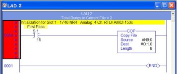
Then you probably have something in your program that looks similar to the picture below. Its used to configure the module. The configuration information is held in N9:0 in the example below and written on first scan to the modules configuration word. The orginal programmer probably did not use the advanced config to configure the module he/she just set to bits in the configuration word ( N9:0). If you use the advance configuration and set to enable you can then make changes with the feature ( the advance config)

Post your .rss file ( zip it first) and we can pin this down with your actual program.

configWord.jpg
 
At home and can't open the file.
Get out the manual for that card there is a configuration like Mickey said. You will have to look at the bit of a word for configuration.
From memeory bit 15 is the enable bit maybe.
 
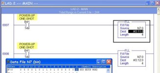
See picture below for how its being configured in the file you posted. And a pdf for what each bit means.

You will have to make changes using the configuration word N7:0 with the pdf provided or delete the "FLL' instructions and use new "copy" instructions created by the software when you enable the advance configuration method.

moduleConfig.jpg
 

Attachments

  • 1746NR4.pdf
    34.4 KB · Views: 34
Last edited:
which channel (specific input address) is giving you the problem? ... or is it more than one channel that's acting up? ...

is the data also fluctuating when you look at the address in RSLogix500 - or only when you look at the HMI screen? ...

are you sure that all of the connections are good and tight? ...

if you disconnect the actual RTD and temporarily connect a spare RTD (just hanging in the air) does the reading settle down? ... if it settles down with the "test" RTD, does it start to fluctuate again when you "ground" the test RTD? ...

along the same lines ... can you temporarily "unground" the actual RTD for a quick test? ... (for example: take it out of the well and let it hang in the air) ...
 
when the temperature is fluctuating, check the values stored at the following locations:

O:11.0
O:11.1
O:11.2
O:11.3
O:12.0
O:12.1
O:12.2
O:12.3

use the decimal radix setting on the datatable ... are all of these values set for 2880 ? ...

what is the significance of input I:1/6 ? ... specifically, what makes this input turn ON and OFF? ... this address is documented as "CONTROL POWER INPUT" ... it is used with an OSR instruction to (among many other things) configure the RTD inputs ... this technique is not the way things are normally done ...
 
I'm a little confused about the pictue of my ladder (rung 7). It shows in the FLL instruction O:11.0. This is an input module, right?
This is happening on all of the acid tank's (temp bouncing around). Put a new RTD in and it had no affect. I can't remember if it has always done this or not. Calibration tech swears it wasn't doing it at last calibration (6months ago).
 
It shows in the FLL instruction O:11.0. This is an input module, right?

yes, it's an INPUT module - but it's a "fancy" one that needs to be configured in order to work correctly ... the OUTPUT addresses are sent to the module to configure it for the specific setups that you require ...

(remember from the PLC-5 class how we CONFIGURED the analog input module by sending "configuration data" to the module with a Block Transfer Write instruction ... the SLC-500 system doesn't use a Block Transfer - instead it configures this type of analog card by sending the "configuration data" through the OUTPUT words ... the idea is the same - but the mechanism is different ...)

try to answer the questions we've been asking above ...
 
(remember from the PLC-5 class how we CONFIGURED the analog input module by sending "configuration data" to the module with a Block Transfer Write instruction ...

Yes, I remember that. I was trying to apply it to this. I think you may have even stated that it was different with the SLC.
 
try to answer the questions we've been asking above ...[/quote]

I think this will cover it:

O:11.0 thru O:11.3, and O:12.0 thru O:12.3 all have a decimal value of 2880.

All of the temps are bouncing-around, on the laptop as well as the HMI. Mag starters for the heaters are going on/off/on/off, as well, in response to the temps it's trying to keep. It is doing it to all the tanks.

At this time, there are parts in all of the tanks so I'm unable to pull an RTD from the tank without affecting the process. I will try tomorrow, if production will let me have it.
Thank you all for your input.
 

Similar Topics

This is my first run in with this setup. I've been all through the forums here searching for any information I can latch onto. Reading through...
Replies
10
Views
2,950
If anyone has one they'd like to sell, please PM me. Alternatively, if anyone has two temperature transmitters (4-20mA), please do the same. The...
Replies
0
Views
1,289
I need help in identifying the fault with a 1746-NR4 RTD / resistance module. The hardware is a SLC500 1746-NR4 module inserted into slot 3 of a...
Replies
0
Views
1,292
Hi,, I used 1746-NR4 module with 1000 ohm potentiometer. How to connect potentiometer to the module and how to configure it? Thank you for help...
Replies
1
Views
3,080
Hi Just programming and configuring an 1746-NR4 card for an SLC system on the Configure box drop down menu for Types of Input I have 2 sorts...
Replies
8
Views
13,971
Back
Top Bottom