1769-SM2 (modbus module)

Ok, here are printscreens of all necessary adjustments.
Thanks for screens but I did similar in my project. I attached it.

I tried again to connect device in single mode. Nothing...CH1 Red Blinking on SM2 only. (I set SW2 in 1X).

Then i set SW2 in 5X and connect two devices. Diode CH1 didn't blink, after I reboot PLC, wait some time - it begin flash again red...

What I think:...

1) I use 1768-L43 (rev 20.13). Is it compatible with SM2?
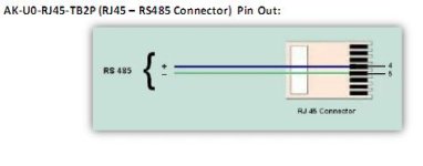
2) Connection to SM2 module. I connect how it's on picture.
attachment.php


1111.JPG
 

Attachments

  • single_mode_screens.zip
    207.8 KB · Views: 36
  • multi_mode_screens.zip
    263 KB · Views: 36
@ Mxm_88.. You have the SM2 config setup somewhere between MB master and DSI VSD master...

Ditch all the parameters other than...
[07]-5 (Modbus)
[14]-1 (19,200)
[15]-? (whatever parity is set in the slaves)
[16]-2 (rx delay, or intercharacter timeout)
[17]-8 (tx delay)
[18]-1 (timeout)

If the SM2 switches are in "contr" & "5x", the above (after a power cycle..) will setup the ch1 port as a Modbus master @ 19200, ? parity (need to match the slave), and appropriate timings..

If you set it up like this, without any messaging in ladder, and you still get the blinking LED on plugging in the Carrel device, it has to be an issue with the Carrel units configuration. The SM2 is only able to be used as a master, it cant be a slave...
 
Lemming said:
@ Mxm_88.. You have the SM2 config setup somewhere between MB master and DSI VSD master...

Ditch all the parameters other than...
[07]-5 (Modbus)
[14]-1 (19,200)
[15]-3 (8-N-2) <<< From the pCO1 Manual for Modbus Slave Protocol
[16]-2 (rx delay, or intercharacter timeout)
[17]-8 (tx delay)
[18]-1 (timeout)

mxm_88,

Parameter 15 [RTU Format 1] and 30 [RTU Format 2] should be set to 3 for 8 data bits, no parity bit, 2 stop bits.

If that is not all that is wrong, I may have other suggestions, but see how that goes first.

Regards,
George
 
mxm_88,

Parameter 15 [RTU Format 1] and 30 [RTU Format 2] should be set to 3 for 8 data bits, no parity bit, 2 stop bits.

If that is not all that is wrong, I may have other suggestions, but see how that goes first.

Regards,
George

That's not what I have shown in the manual... There might have been a new H/W revision since I last looked thou...

Capture.JPG
 
Thank you very much for your advices!

Ditch all the parameters other than...
[07]-5 (Modbus)
[14]-1 (19,200)
[15]-? (whatever parity is set in the slaves)
[16]-2 (rx delay, or intercharacter timeout)
[17]-8 (tx delay)
[18]-1 (timeout)

1) How do you choose rx/tx delays and timeout?
2) Parity. Parameter "3".
In manual on Carel pCO modbus card says about it:

The protocol used in the pCO allows it to be connected to a Modbus supervisor in TRU mode with 8 bit encoding and error handling using a 16 bit CRC.
The transfer of the packages between the peripheral and supervisor follows the RTU mode (frame interval>= approx.. 3.5 T, T being the communication time for one datum).
The data communication is asynchronous serial, 8 data bits, 2 stop bits and no parity (in total 11 bits/datum), across a RS485/RS232 serial line.
The communication speed can vary from 1200 to 19200 baud.

3) I finished working there yesterday. I took data to SCADA from Carel using MOXA NP 5150.

I take a vacation next week. After that I will have some work there again - two devices (UPS, APC, AP9622 cards) will be added in modbus net.

So I will try test again SM2 module.o_O I hope it will work eventually...
 
Thank you very much for your advices!
1) How do you choose rx/tx delays and timeout?.

Time out I always set to 1 second, which is minimum... The RX delay is the intercharacter delay, or delimitation of end of packet. The default is 3.5 charcter spacings, which is baudrate dependant. I have found the default can be a fuzzy parameter, and sometimes more helps stability..

Enjoy your time off :)
 
Surprised by this, didn't think there was any message queing in the module. i've always cascaded the messages based on previous .DN or .ER

I have one slave at CH1 and other at CH2 but all four messages go at the same time so I guess there is some sort of queuing inside SM2.
 
Lemming,

We might be on to something here...

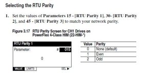
You are working off of firmware v1.xxx options for the 1769-SM2; manual 2006. As per your attachment, the RTU serial framing parameters are called [RTU Parity x], and you can only select options...

[RTU Parity x]
0 (8-N-1)
1 (8-E-1)
2 (8-O-1)

...all of which only allow 1 stop bit.

I am looking at the firmware v2.xxx options for the 1769-SM2, released since 2010. They made changes to the RTU serial framing parameters. They are now called [RTU Format x], which makes more sense as Parity is only one aspect of the framing. They added the options 3, 4 and 5 to set the parity for 2 stop bits for certain slaves that adhere to that standard.

[RTU Format x]
0 (8-N-1)
1 (8-E-1)
2 (8-O-1)
3 (8-N-2)
4 (8-E-2)
5 (8-O-2)

mxm_88,

It sounds like the 1769-SM2 firmware is at v1.xxx, which is why you cannot set option 3 (8-N-2). If you can confirm this, and if at v1.xxx, then you need to flash the module to v2.xxx to support the pCO Modbus slaves, which use 2 stop bits. You can do this via the CompactLogix across the backplane to the module.

The recommended [RTU Rx Delay x] when using a PowerFlex 4 drive at 19,200 baud is 2ms and 8ms for [RTU Tx Delay x]. The [RTU MsgTimeout x] is a default 2secs. You may need to increase this. As you will be using 19,200 baud to the slaves, I would start with these values and see how you go.

They have also made improvements to the modules tolerance to intercharacter delay for received packets, and corrected issues with the Modbus Master read/write commands. So either way it will serve you well to go to v2.xxx.

Here is the Release Notes for firmware v2.xxx. It can assist you in determining the current firmware version, and in how to flash the firmware to v2.xxx...

Publication 1769M2-RN001A-EN-E – June, 2010


This is the latest User Manual for the 1769-SM2, which includes the v2.xxx updates...

Publication 1769-UM013C-EN-P – June, 2010


(Supersedes 1769-UM013B-EN-P – January, 2006).

Regards,
George
 
I am looking at the firmware v2.xxx options for the 1769-SM2, released since 2010.

Good to know :), I haven't used one probably since 2009, so missed the update. Seems worth applying thou.

As an aside, had a site with 3 x SM2 with a mix of package plant and Beckhoff MB RTU IO. We added a forth SM2, and ended up with the PLC faulting a couple of times with out any good reason. The dump file to RA finally came back with the maximum messages running across the 1769 backplane should be limited to 4. In my case, each channel was running cascaded so was potentially 11 with 4 modules. Have consolidated the IO, moved back to 3 SM2, and throttled some of the nodes which has sorted, but unless it is mentioned in the V2 manual, dont think I ever found it documented anywhere...
 

Similar Topics

Hello everyone. I'm trying to communicate a Controllogix L36ERM with a 1769-SM2 Modbus module to a Schneider-electric Altivar 312 Modbus motor...
Replies
7
Views
2,485
Hi All. I am trying to relocate a simple MODBUS system from a MicroLogix 1400 (on channel 0 set as a Modbus RTU Master) to an CompactLogix SM2...
Replies
1
Views
1,817
I am using a 1769-L35e with a 1769-SM2 (latest firmware) to communicate with a MicroMotion transmitter (9739MDV) that automatically detects serial...
Replies
7
Views
3,564
Hello Everyone. I am using a 1769-SM2 Module to communicate Modbus RTU to a third party device, using the first serial port. I am using MSG...
Replies
0
Views
3,349
Dear all! I am trying to Communicate with one temperature controller(Honeywell DC1040) using Miglogix1500&1769sm2 module via Modbus...
Replies
4
Views
5,716
Back
Top Bottom