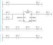
Alyelhefni,
If you want help troubleshooting your program, you must turn on "View, Sybolic Addressing", then take the pictures of your networks. Without any English text symbols, I cannot help you very much with figuring out why it is not working. Apparently you can't figure it out either, and I can see why. Without the symbols it is a coded puzzle with no key. At least you could type in Titles for each network, with each Title being a sentence that explains what the network is supposed to DO, and maybe add some network COMMENTS that list a NAME for each address used in that network.
Here are a few things I can see even without any symbols, titles, and comments:
(1) You need at least TWO 2-second timers. I see only one (T2). One 2-second timer is to stop Conveyor #1 for 2 seconds while S2 looks at the Product to decide if it is Faulty or Good. The other 2-second timer is to measure the ON time of the FLAPPER to kick off Faulty Products.
(2) Using Set and Reset relays makes your program approximately 2 times longer.
(3) I am not familar with the type of Counter you are using, but for most of the counters that I do no about, the Trigger or Set input must be wired to a device that goes on and off, such as the Sensor # 3 that you are supposed to use. That means that you need a ---||--- normally open contact connected between your power rail and the Counter S terminal. Without that it probably will not ever count. Also, this counter can not be be reset with one of the Sensor inputs alone. The sensor Inputs alone cannot tell you if the Full Box has been moved down Conveyor #2 AND a new box has been moved into the Fill Position.
(4) Sensor 4 can tell you that a new box is present, but by itself S4 CANNOT tell your program all it needs to know (that S4 was ON, then OFF, then ON again), completing one box of 24 products AND moving a new box into position. These conditions CAN be determined by a combination of looking at the Counter bit AND the S4 bit AND the Conveyor #2 Output bit. Without knowing these things, your State Diagram is just a pretty picture, fat, dumb and happy that it knows nothing of some states that exist but are not shown or used. That is the problem with State Diagrams: they only work if every single little unnoticed but possible state is included. If not, there are gaps in the logic. Loooking at your 6 States, I can see that there probably are about 10 to 15 States in this project. I handled this state-logic gap in my program by adding another Timer T2 (others are T0 and T1), set for 2 seconds also. When Conveyor #2 starts, this timer T3 is to allow a Full Box of 24 to move off of Sensor S4, so that it turns on a "MOVE_FULL_BOX" M relay, self-seals itself ON, and S4 then goes from ON to OFF (no longer sees a box). Then Conveyor #2 moves the full box downstream for some time period (who knows how long to get to the end?), at least long enough for S4 to go OFF. Now we must wait until a new empty box shows up (drops down from above?) and S4 goes ON again (completing the ON-OFF-ON cycle of S4). Then we can STOP Converyor #2 (I think it is Output Q1.2 in your program), and then also allow Conveyor #1 to restart.
(5) I know Siemens loves the Count Down counters, but in this case you are counting Products UP as they go from 0 to 24 to fill a Box. Why make it complicated and counter-intuitive? The Count Up Counter that I used is shown in the picture. The Preset Value can be a simple constant of "24".

Last edited:


