sparkyinak
Member
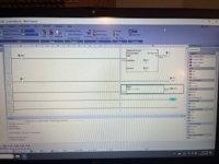
I have both an Automation Direct Click Plus PLC and a EA3 series Micro HMI that I’m getting a feeling for before a big project since I haven’t use one before. See attached pics.
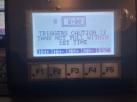
The first pic is practice program and it shows the whole program that’s is currently on the PLC. It’s just an on delay timer (T1) that reads its time from data register DS7 which is a single word integer. The next picture is a screenshot of the HMI where DS7 gets its time data inputed. DS7 is the result of a math problem from line 3 where it doubles of the hour (HH) input which is data register DS6 and then adds the minutes (MM) input to for a total for data register DS7.
On the HMI screens, the number in the center in the square is the time entry, and the number in the upper left of the HMI screen is DS7 which is the result of the PLC math from line 3 of the program. Line 3 is to convert the hour and minute time setting to minutes for the timer in line one. I know, the 2 should be 60 to convert the hour settings to minutes. I temporarily changed the 60 to 2 to speed up the testing versus waiting hours. That’s not the problem
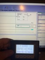
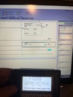
As I run the program and monitor the PLC, like in the next two pics, as more time is added through the HMI, the math starts out correctly and DS7 adjusts according. The number in the upper left of the screen on the HMI and the result of Line 3 and timer setting on line 1 which is DS7 should all 3 equal the same, all the time. As more time is added, the number in the upper left of the screen and the goals on the PLC fall out of sync. Picture 3, DS7, the upper left number on the HMI is in correct because as the formula on line 3 of the program doubles the hours and add the minutes so 2x8+0=16, not 10 as its shows so the HMI is in correct. In picture 4, the PLC is incorrect. The time on the HMI shows 0:10. Using the same formula, the number on the HMI and on the computer screen should read 10. The HMI is correct this time but now the PLC is off.
As more time is added, the worse it gets. The parentheses in the math problem are only there to see if that fixed the issue and it didn’t. It will do the same thing with or without them. It’s not random errors but consistent. Like on the picture 4, the count goes, 8, 9, and it skips to 16, 17… Skips the same numbers going back.
Any ideas what could be causing it? The proposed project will have several timing adjustments that are critical and currently having some genuine concerns. Am I doing something wrong? Is it a known issue or do I have a system that just can’t add beyond 10?


