Analog alarms - Ladder logic

bjarte

Guest
B
Hi !

I am programming AB CompactLogix, I have 32 analog signals that requires HH,H,L,LL alarms with individual limits and deadband, delay and latch. I know how to program but it requires a lot of code. Anyone that can help me doing this quick without all this code. I need something that can make my program simple and that I can reuse many times.

Bjarte, Norway
 
First of all, you should register on the site. We like to know more about you, and we can follow your threads easier.

With the community service stuff out of the way, here are some thoughts:

1. I'm not sure if CompactLogix offers this, but ControlLogix lets you configure HH, H, L, LL, etc. right in the IO card configuration. Will that help? It may be quicker than writing a bunch of code. If you're considering it, I'll warn you that those limits are more-or-less fixed. You can't change them at run time without resetting the module.

2. If you have a "standard" chunk of code, where very little changes, take a took at an L5K file. This has been discussed here a few times. L5K files are a handy tool for RSLogix5000. You can use macros, spreadsheets, and other basic tools to autogenerate chunks of code.

AK
 
I thought you could write function blocks with AB, or is that only
with that cool Siemens Step7 software??
 
Function block is available on certain version of RSlogix5000, I believe. It's the "pro" version I think.

It's not that hard to do copy and pasting with Ladder Logic either. I would build a user-defined Tag structure for Analog alarm first to make things look cleaner. Once you built that first chunk of code, copy and paste it, then select the code and do a Search and Replace. Shouldn't take you more than a minute for each analog input.
 
What about indirect programming? Put your code in a routine. Create some Input Parameters (current input value, HH, H, L, LL Limits...) and the requiered return parameters. Call this routine for every input.
 
I have used Klaus's suggestion many times with the PLC-5.
Move the parameters for the first analog into a "work file", call the routine, move your work file data to a storing location, return to main ladder, repeat for all other analogs.
 
You can also create a subroutine to which you can pass parameters such as analogue input (integer), limits LL,L,H,HH (integer). The output parameters would ofcourse be the alarms (bits/flags).

In essence you would have only have to write one subrouting such as JSR which would be executed for each analogue. Hope this helps.
 
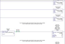
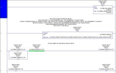
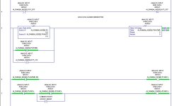
I'll start you off. It's not really a silver platter, maybe more of a copper one as I've left out some logic and how the tags are structured (there is a user defined one used).

Standard analog input routine:

[attachment]

ana_in.jpg
 
analog alarm routine cont'd:

[attachment]

That's all I'll post for now. There is no deadband used and I've only shown the code, not the tag configuration. I'll leave that up to you to try. Post again if you have questions.

grs

ana_alm_2.jpg
 

Similar Topics

Hi all. I have 1793-IE4 (4)analog inputs modules in a 1794-ADN IOFlex DeviceNet Rack. I cannot find if I can I have access to individual channel...
Replies
1
Views
34
Good afternoon, I am currently working with an HMI/PLC LP-a070 and I require at least one analog output, but the PLC does not have one. I was...
Replies
5
Views
126
Hi all. Customer wants analog faceplates really bad, even if we explained that it doesn't make much sense in his process. What he wants to see...
Replies
5
Views
135
I'm having trouble calming down 2 Tempo Sonics. I'm using Studio 5000 CompactLogix my Raw value is jumping around from 8575.0 to 8755.0 at a...
Replies
30
Views
1,189
I cannot add SLC500 analog input tag (I: 8.3) to EZSeries Touch Panel Editor (V 5.3). I used all the listed tag datatype but it all says "Invalid...
Replies
10
Views
285
Back
Top Bottom