Automating two seperate linear actuators

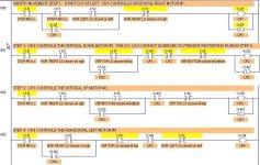
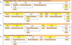
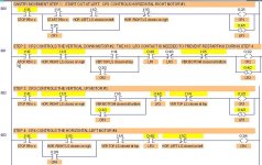
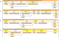
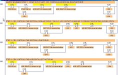
Try to make yours look like this. I think you need to add a N.C contact for LR3 on the 2nd rung as shown in the attached picture. Add Stop buttons so that you can really stop it at any point. Also add the reset rung at the end to reset the latched relays. Otherwise they will stay on until you turn off the power.

Gantry Movement- Richard0956.JPG
 
Last edited:
Is this supposed to be an actual hardware implementation or is it intended for a plc? that is somewhat unclear to me at this point. The way the OP refers to things it seems it is supposed to be hardware.

Now that the basic sequence is down, what do you do if the horizontal gantry isn't all the way to the left when you press start?

Always looking to stir the pot.
Keith
 
Keith,

It is a hardware implementation, but I have simulated it on the LogixPro simulator.

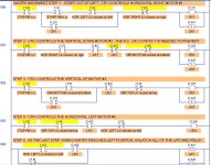
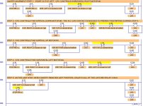
Here are pictures of the 5 steps, showing the limit switch positions after each step has been started. This circuit does make it all the way through.

Because the latched relays are used, the circuit could be simplfied some by used the latched contacts in places instead of the limit switches.

Gantry Movement- Step 1.JPG Gantry Movement- Step 2.JPG Gantry Movement- Step 3.JPG Gantry Movement- Step 4.JPG Gantry Movement- Step 5.JPG
 
Last edited:
OK. So richard0956 will need to actualize the latch relays when he goes to hardware. They don't make those ***y (L) and (U) instructions in hardware, at least not the way they are shown. He could use magnetic latching relays for those spots.

I'm still not sure how the thing gets going if the horizontal carriage is not at the far left limit switch when the start button is pressed. Then again, he may not be specifically concerned about that.

Keith
 
Oh I see things have moved on whilst I've been drawing my circuit for 4 motors to drive a vertical and horizontal gantry.

I've not examined yet at what has been posted (I will) but here is my circuit. I does not show how to reset the latch relays.

At the moment I've been seeking to understand what a circuit would look like using just electromechanical relays. Then later I want to examine how you would achieve the same thing with a PLC.

The following is what I wrote in relation to my circuit:

------
After further thought I've produced my circuit for automating vertical and horizontal gantries with 4 DC motors. Pressing Start button initiates a sequence of the horizontal gantry going to right end stop. Vertical gantry then goes down to it's end stop and then goes back to home, then horizontal gantry goes left to home.


CR1 is associated with a motor M1 which takes H gantry right.
CR2 is associated with a motor M2 which takes V gantry down
CR3 is associated with a motor M3 which takes V gantry up
CR4 is associated with a motor M4 which takes H gantry left


I have not shown the motor circuits which may be required to be interlocked.


I hope the circuit I've drawn would pass muster.


I'm making the assumption that once a latch relay is energized any further energizing does not reset the latch contacts.


Here is the explanation:


Ladder #1: Pressing start energizes CR1. Horizontal gantry moves right. CR1-1 seals, so there is continuity after button is released. Lim1 is vertical gantry top limit switch. This ensures CR1 will only be energized if the vertical gantry is at it's top position out of the way of the horizontal gantry. LR1-1 is NC latch contacts associated with LR1.


Ladder#2: When the horizontal gantry hit's right end stop, Lim2, a horizontal gantry right limit switch closes. That energizes latch relay LR1. LR1-1 contacts open and CR1 de-energizes. CR1 can only be re-energized after LR1 is reset. This avoids accidents if Start is pressed accidentally at some inconvenient point to set M1 running.


Ladder#3: Lim3 is a horizontal gantry right limit switch. When the horizontal gantry hits right end stop Lim3 closes energizing CR2. CR2 controls M2 which drives vertical gantry to bottom end stop. LR2-1 are NC latch contacts associated with LR2.


Ladder#4: Lim4 is a vertical gantry bottom limit switch. When the vertical gantry hits bottom stop, latch relay LR2 is energized. Therefore, LR2-1 opens and stays open. This de-energizes CR2 and and thus M2 until a reset of LR2.


LR2 (and not a simple NC limit switch in series with CR2 circuit) is necessary: If there was no permanent break arranged in the circuit, there would be an instance when M2 would be energized when the vertical gantry hit top.


Ladder#5: Lim5 is a vertical bottom limit switch which closes when the vertical gantry hits bottom stop. When that happens CR3 is energized and M3 moves the vertical gantry to the top. CR3 seals Lim5, in order to maintain continuity when Lim5 opens as the vertical gantry moves to the top. LR3 is a latch relay that operates LR3-1 LR4-1 are the contacts associated with LR4.


Ladder6: Lim6 is a vertical gantry top limit switch. When the vertical gantry hits the top end stop, this closes energizing LR4. LR4-1 contacts open CR3 And M5 are de-energized. LR4-1 contacts stay open until LR4 is reset.


Strictly speaking you do probably do not need LR4 and it's contacts. A simple NC limit switch at top end of the vertical end stop will serve to stop M3. For this circuit to be energized again vertical gantry must be in the bottom position which is probably unlikely to happen.


Ladder7. Lim7 is vertical gantry top limit witch, which closes when vertical gantry hits top. CR4 is energized, so M4 drives the horizontal gantry back to home. Lim8 is a horizontal gantry left limit switch which opens when horizontal gantry hits left end stop. Latch contacts LR3-1 only close after CR3 is energized. If this were not the case CR4 would be energized right from power switch on because the vertical gantry is at the top before the Start button is pressed. Also when the vertical gantry is driven to top by M3. So, it is essential LR3 is in circuit.
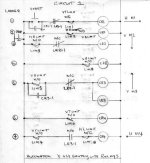
Automation V and H gantry 4 DC motors.jpg
 
Last edited:
Another question will arise

1.) what type of motor you use ? 3 phase or single phase.

2.) why use 4 unit motors?

3.) any gear box installed with motor ?

4.) are this motor c/w high speed and low speed selection?

5.) what type of limit switch you use? are this limit switch safe to use?

6.) how you calculate the motor load ? how you set the O/L?

7.) if you stop on middle operation what system holding the load? if continues what speed you select? low speed or high speed ?
 
I hope the circuit I've drawn would pass muster.
You are getting there, but here are 2 problems that you mentioned yourself:
I do not show how to reset the latch relays. I have not shown the motor circuits which may be required to be interlocked.
How ARE you going to reset those latched relays? Unless there is a method, they will stay latched forever after the first time.

Your STOP pushbutton looks like it has a N.O. contact, and a Stop PB should always use a N.C. contact. Maybe it is just a sloppily drawn, but often that is enough to cause someone else to make a mistake. The way you have your STOP located and wired, it will have to be a maintained-contact selector switch (or Push-OFF, Push-ON pushbutton) in order to stop any of the motors at any time. With a maintained-contact STOP, you might as well make it a ON/OFF selector switch, and do away with the START pushubtton and seal-in contact. As you have it wired now, using a momentary-contact STOP pushbutton, you can only STOP the first motor. After the first step, it will keep going (unless you use a different STOP PB). The problem with a maintained-contact ON/OFF switch is that if someone leaves it ON during a power outage, the circuit will reactivate when the power comes back on.

You added a 4th latching relay, when your first circuit with only 3 latches worked okay (with a little debugging).
 
Last edited:

Similar Topics

There is a very old manually operating hydraulic forming press in our production. At the moment it's out of operation due to some issues with the...
Replies
17
Views
6,118
As a newcomer to RSLogix, I keep reading about (and am quite interested in) how companies automate tagname creation and have libraries of...
Replies
15
Views
5,647
Since rslogix 5000 does not have vba, is there a better way to automate programming tasks than using vba to generate an L5X file?
Replies
1
Views
1,823
Question for you guys who work for yourselves or for companies as programmers: What is the process by which your customers convey to you the...
Replies
10
Views
3,811
I'm looking for a quick advice. To all you guys that have automated a machine, what are the steps that you follow to developed your project? Do...
Replies
12
Views
3,112
Back
Top Bottom