Blower Overvoltage

Without question at some point the motor will burn up.
Depending on the VFD manufacturer, there will be a motor model in the VFD that attempts to do a dynamic calculation of the thermal load of the motor. And you can usually configure the desired response to a calculated thermal overload, usually it is to limit or reduce the speed.
This motor model will not be perfect, but much better than any regular overload relay.
Like I said before, any motor driven by a VFD and especially if does not operate at a constant speed, it is highly recommended to protect the motor with winding thermistors. Any VFD have thermistor inputs for exactly this purpose. If you do protect the motor with thermistors, you can pretty much fool around with the VFD settings, and the motor will not burn up.
As I have said before I think your motor is actually driven in reverse by the air flow through it when you try to start it that why you are getting a buss overvoltage fault.
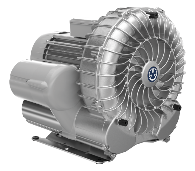
I suggest some investigation in the field. With these vacuum blowers you probably cannot see the motor shaft, but you can observe the fan end of the motor when doing the flying start. That will clear up if the blower is rotating in reverse.
 
Rereading the 1st post I realise that you probably cannot observe the error situation.

Watching the Output Frequency when it starts regardless of success or failure is interesting, hz flashes up around 58-60 for a split second, then down to the normal 0-40hz ramp
Is the drive set to sensorless vector control or u/f ?
Maybe this is a case where simple u/f is best.

edit: And maybe increasing the startup ramp from 1s to something more realistic will help. No matter that the blower must start as fast as possible.
 
.... You can also see on the attached doc that when drives fault the HZ is always in the 55-60hz range which these never spin at. Any ideas or advice is greatly appreciated.

...
Perhaps the main problem is not electrical but rather the pipe installations.

In centrifugal fans, the absorbed power varies with the third power of the revolutions !

These types of blowers cannot operate with the inlet and outlet openings free since they absorb more power than calculated.

Normally valves are installed at the inlet and/or outlet to adjust the desired operating point within the characteristic pressure-flow graph of the fan.

Surely when reaching 55-60Hz the power absorbed is excessive.
 
@Ife.

It is a regenerative vacuum blower.
Something like this:
https://beckerpumps.com/wp-content/uploads/2022/09/Becker-Single-Stage-Regen.png
The startup is not as heavy as a big centrifugal fan. It takes a few seconds.
I dont think the blower spins up to the 55Hz. It is only the VFD that tries to output 55Hz, then immediately go back to 30-40Hz.
 
I also installed some regenerative fan in the past, but in both types of fan you have to regulate the desired flow with valves.

The same rule that power varies with the cube of revolutions also applies to regenerative ones.

If it is started without restrictions in the pipes, consumption increases greatly at high revolutions.

Furthermore, when running without restrictions, the efficiency is very poor, it heats up the air a lot
 
I agree that there should be a flow restriction.
In the application I have seen, there are valves for activating the vacuum when needed. So startup is with the valves closed.
 
I agree that there should be a flow restriction.
In the application I have seen, there are valves for activating the vacuum when needed. So startup is with the valves closed.

Or rather, regulate the valves of each blower one by one for the desired flow and pressure at the desired revolutions and then leave them set.

Another option is to limit the frequency to < 55 Hz but with the valves open. It would be a more energy efficient solution, since a half-closed valve creates a loss of pressure and therefore a loss of energy that is converted into heat.

Something that should be resolved by the installation designer.

By the way, this is the first time I've heard that this type of fan is called regenerative, I had always known it as Siemens ELMO type
 
In our flywheel application that was behaving very similarly to OP's, the blip to full frequency was the drive scanning to figure out where the motor was at the time. It then jumped to where it figured out the motor was and started its "full power" ramp from there. That behavior was part of the flying restart and occurred in V/Hz and SVC modes.

The CCW trend wasn't super helpful for me. The sequence of events was incorrect. It showed the OV fault happening first, before the bus swelled, then the freq command dropping to 0, and then (after a couple of seconds) the DC bus swelling. That led me down a rabbit hole that was the wrong path entirely. Go ahead and do your trending but be aware that, at that short sample rate, the order of events isn't trustworthy in these. That conclusion was verified by our distributor rep and Rockwell.

I keep coming back to strongly recommending a larger brake resistor. We used ProposalWorks to size it based on a 50% overhauling load (OHL). Since then, it has run fine for several months where it wouldn't run without it for more than 8-10 minutes even when it would initially start, which it wouldn't always.
 
You are spot on with your overload setting at 125% and your torque limiting at max (200%). Try starting that fan with an across the line starter and you will see 600% FLA as it gets over the hump to full speed. The motor will require more than 100% torque to start a fan - even with a VFD. So it does not surprise me that you can't start it with less then 200% Torque Limit.

I do believe that brake resistors are your friend
 
In our flywheel application that was behaving very similarly to OP's, the blip to full frequency was the drive scanning to figure out where the motor was at the time. It then jumped to where it figured out the motor was and started its "full power" ramp from there. That behavior was part of the flying restart and occurred in V/Hz and SVC modes.
So what you are saying, with a flying restart this behavior is unavoidable, thus causing the overvoltage when there is no brake resistor ?
It is not possible to tell it to try and catch it from 'below' so to speak ?
 
The quick scan up to max frequency is not causing the problem at all. It's just the drive figuring out where to start its ramp during a flying restart. It does delay the start of the ramp by a few seconds so if flying restart isn't needed, don't do it. If the high inertia load can still be spinning when you initiate a start, then flying restart is likely necessary to avoid an overload fault (not over-voltage).

In our application, we tried a LOT of different parameter changes over a week's time, with a LOT of trending, in V/Hz and SVC, with tweaking ramp times (even changing the ramp time on the fly). We were able to improve the situation but not resolve it until we installed the larger brake resistor. That solved it completely without any "fancy footwork". With the right resistor, the presses are running great in simple V/Hz with a reasonable accel time (5-10 seconds as I recall) and work in either ramp or coast to stop.
 
An encoder might lessen your issues a bit.

If the load is winding down from a stop, then you have to restart before it's at rest, an encoder could fill in the blanks.
 
Last edited:

Similar Topics

Customer want to use contactor for their 5HP motor blower application. im leaning to VFD. anyone use contractor for blower application...
Replies
9
Views
201
Good Evening , I have an " Oddball " Blower Motor , and really do not have any U.S. support . It is a manufacture called EBM Papst and the...
Replies
4
Views
1,144
Any takes on whether this is the end of GE and what will happen to their industrial automation products...
Replies
15
Views
6,488
Hello, Does anyone have an alternative idea to correlate the speed of a VFD on an aeration blower to a desired Dissolved Oxygen setpoint...
Replies
10
Views
4,399
A dust collector blower fan motor 18kW, previously run by a star-delta starter, has been replaced with a VFD( Brand: LS, Model: SV-iP5A). Our...
Replies
38
Views
11,787
Back
Top Bottom