Can a SLC 5/04 GEQ cmd compare floats or do they have to be integers? EOM

OK, here's the situation.

I've got a multiply block using a working register as the destination (working register is a register I use over and over in the program for intermediate results. For instance, during certain states of machine operation I double the alarm and trip values, so I take the normal A/T value, multiply by 2 store in the working register and use in a comparison block which is enabled by the state bit). The problem is, even though the comparison block is in the rung immediately after the multiply block the comparison does not work. If I hard code the multiplied value into a dedicated register it does work. So here's my question, are the comparison blocks executed in the order drawn or not? I have worked on hardware platforms where they are not solved as drawn and that's the only thing I can figure here.

If this is too hard to read just ignore it, I wish I could write like Paula.

Thanks,
Jim
 
jimpad said:
If I hard code the multiplied value into a dedicated register it does work.

Can you explain that a little better? Is a screenshot possible?

jimpad said:
So here's my question, are the comparison blocks executed in the order drawn or not?

Drawn? If you are talking about how the PLC solves the logic; the ladder scans left-to-right, top-to-bottom.

Are you comparing or multiplying integers and floats in the same instruction?

I am not sure about mixing floats and integers in these math/comparison instructions. I don't recall ever having done it. I have ran into problems mixing floats and integers in a CPT (compute) instruction. Rule of thumb for the compute instruction is keep them all the same - integer or float, but I can't say the same is true for these instructions, but I would look into the possibility.

Someone here can probably clear this up.
 
1. How do you do that quote thing?
2. What I mean by hardcode is dedicating a register for use in the comparison rather than the working register.
3. Yes, I'm talking how the logic is solved.
4. All floats.

I must be doing something stupid I'll spend some more time on it.

Thanks for response.
Jim
 
jimpad said:
How do you do that quote thing?

Look in the lower right corner of each post. There is a "quote" button. Click it and you will see the tags to get the text formatted like it is when posted

jimpad said:
What I mean by hardcode is dedicating a register for use in the comparison rather than the working register.


I don't think there is much of a difference between a "working register" and a "dedicated register". Are you saying that you replace the "working register" (an address) with a constant?

Can you give a screenshot of what you are doing?

Here's what I am thinking so far:

rsl500.gif
 
93 I really appreciate your assistance.

I think I'm on the trail of it now... my working register seems to be getting messed up somehow. I've shutdown the subr where I do extensive math using the working register and now my A/T logic seems to be working. So, I believe my working register may be overflowing and maybe that precludes using that register for the remainder of scan. I did see where the S2:0/2 bit got set momentarily so I'm thinking perhaps this is an indication of a problem. The help file says that bit gets set when the result of a math or data handling instruction is zero... I would think that would be quite common but since they a special bit for it I'm thinking maybe that's an indication of a problem.

Thanks,
 
jimpad said:
I think I'm on the trail of it now... my working register seems to be getting messed up somehow. I've shutdown the subr where I do extensive math using the working register and now my A/T logic seems to be working.So, I believe my working register may be overflowing and maybe that precludes using that register for the remainder of scan.

You are using floating point, right? The number would have to be extremely huge to overflow. I think the fact that disabling the SUB that handles the "working register" takes away the problem tells us that the number is getting overwritten somewhere in there...
 
93lt1 said:


is getting overwritten somewhere in there...
I'm sure it is getting overwritten. The point behind the working register is as long as you use it before it is overwritten you can use the same register for intermediate calculations throughout the program without having to use a new register. In this case I'm using the wr in the next rung, so the value can't be overwritten until I've already used it. But, if the register is overflowed or div/0, I'm thinking the register doesn't work until reset at top of scan.

Jim
 
jimpad,

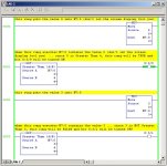
I’m not 100% sure that I know what kind of trouble you’re having ... if this doesn’t help, it might be a good idea to post your code ... anyway ... here is a program which “overwrites” the N7:0 ... notice that the screen display can be very confusing ... secret handshake: with a SLC-500 processor, the screen update is (usually) based on the data which exists at the END of the scan ... that’s why “seeing is always believing” ... in a nutshell, the screen display is not “real-time” ... maybe this is what’s causing your confusion? ...

[attachment]

if the “end of the scan” screen display is part of your problem, then one way to preserve your sanity is to use a new location (N7:1, N7:2, etc.) for each step of your math function ... that way the screen will be able to display the intermediate steps and help you debug any math problems that you might otherwise miss ...

scan example.jpg
 
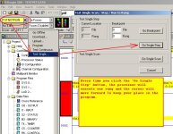
and here’s something that I just KNOW you’re going to love ...

[attachment]

see if this approach helps ... tip: many people work with RSLogix500 for years and never even know that this “single step” feature exists ... it takes a few minutes to get used to it, but once you do, you can move through the program rung-by-rung and watch the values in the memory locations change as each rung gets executed ... party on ...

single step.jpg
 
Jim-

I do what you're discribing quite a bit. There are two things to be a little careful of.

First, you need to be ABSOLUTELY certain that you are either:
A) Only running the comparison when you are sure the preceeding calculation has been run.
B) You are always running the preceeding calculation.

If you use 'intermediate' registers as a scratchpad you need to make sure the equations driving the scratchpad value are run when the comparison is made. This infers putting the comparison directly in parallel with the instruction setting the intermediate value with no conditions before the comparison.

The second is MUCH less likely since you seem to infer that this just plain doesn't work as opposed to it being flaky. But, a processor interrupt, such as an STI or DII, will interrupt the scan in the middle of a rung. I think I was told it will even interrupt the logic in the middle of an instruction but I'm not sure about that. So if you use your work register in the interrupt routine the value can change on you between when you set it and when you use it even if you structure the code as I stated above. But, again, the chances of hitting that exactly right are EXTREMELY small, although it will DEFINITELY happen at some point. This type of problem would usually make the program flaky, not just fail.

Keith
 
Thanks,

Ron,

1. Yes I'm quite familiar with the "end of scan screen" issue. Very nice example thanks for the effort.
2. This is my first project w/AB hardware I haven't used the single step feature but now I'm sure I will. Thanks.


Keith,

I believe the STI was the problem. I created a new wr dedicated to the STI routine and continued to use my old wr throughout the rest of the routines and all seems well now.

I guess I wasn't clear enough in initial description. It was flaky, quite perceptive of you to guess the STI factor.

Thanks again,
Jim
 
oops!

sorry but one of the pictures I posted above has a typographical error in one of the rung comments ... stuff like that drives me crazy ... anyway here's a corrected copy ... now I can sleep tonight ...

[attachment]

and good work on nailing the "STI" problem, Keith ...

scan example.jpg
 

Similar Topics

I have 4 outputs which cycle off-back on, one at a time if more than 1 output shuts off I need to set an alarm I`m wanting to use the compute...
Replies
3
Views
1,893
I’m attempting to send a temperature from a SLC-5/02 to an EZiMarquee display. The vendor said to use a MSG instruction to send the data to the...
Replies
1
Views
93
Hello all. I have a few SLCs in my plant and of late we've seen a weird issue: The system will be running normally and then randomly the outputs...
Replies
2
Views
103
I am working on setting up a Prosoft Datalogger model PLX51-DLplus-232. This unit will be collecting data from a SLC 5/05 on the DB9 port set to...
Replies
3
Views
104
I have a redundant ControlLogix being set up. This program reads a value from a remote site which happens to be SLC PLC. Rockwell mentions SLC...
Replies
2
Views
96
Back
Top Bottom