CCW Timer question

rhaul

Member
Join Date
Jul 2021
Location
yep
Posts
3
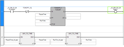
Hi, I've been lurking for about a month now and via the search, I've been able to string together a basic micro820/PV800 project. I've got a simple program that turns a motor on and off with a TONOFF timer, with variable pause/run times being set by the user via the HMI and converted into values. See attached image.

What I now need to do is be able the program to take in a new input (button) and either reset or pause the timer based on which TONOFF cycle it's currently on.

IO_EM_DI_05 is pressed

IF TONOFF_1.Q = TRUE THEN Pause the timer and reinitiate when IO_EM_DI_05 is pressed again

ELSE

IF TONOFF_1.Q = FALSE THEN Reset the timer


I've looked at switching to RTO and using multiple ladder rungs, but I'm getting stuck on the ladder layout.

Any pointers would be appreciated. Cheers.
820prog.PNG
 
Welcome to the forum.


can the program write to TONOFF_1.ET?


if yes, it could store that .ET value at the end of each scan, and if a pause is active on scan N, then, before the TONOFF instruction executes, write the .ET value to set the clock (timer) back to its state from scan N-1.


It's ugly, and may not work, depending how the timer is implemented.


Otherwise the TONOFF cannot be used, and its functionality would need to be implemented with a TON and an RTO, with the RTO providing the OFF functionality of the TONOFF.


Here is a video that uses a TON and a TOF to duplicate the TONOFF functionality.
 
Last edited:
Thanks for the reply, and the edit with the video. Pretty sure that I can work it out from here.

Appreciate the quick response drbitboy.
 
P.S. Huh. CCW does allow modifying the .ET of a TONOFF object, but I was only able to git 'er done via the COP instruction; both MOV and ANY_TO_TIME instructions threw build errors.

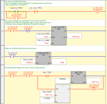
The image below shows the "motor" running, after input [_IO_EM_DI_03 Start Motor] passes a 500ms debounce, and with its run-time extended via input [_IO_EM_DI_02 Extend Run]. The TONOFF reset logic is left as an exercise.

For me, this is pretty ugly: COP wastes almost half of the visible vertical space; CCW feels like Fisher-Price, I guess I got spoiled early with RSLogix 500. So I'd see what it looks like using a TON for debounce and an RTO for the run duration; it might be cleaner.


ccc.png
 
Last edited:
CCW is very clunky and this is coming from someone who uses Visual Studio on a daily basis.

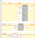
I ended up combining what I learned from the video you linked with some others and came up with this as the solution (excuse the poor quality of the screenshot, I'm being forced to use a computer with 1360x768 res). It uses RTO/TOF as per you initial response.

That's really interesting re the modifying of the ET. I'm going to give that approach over the weekend.

Again, thanks for your help, really appreciate it.

Capture.PNG
 
I was going to say to ignore my solution as it is ugly and kludgy - the fact that I needed to use a COPy to MOVe a DINT means CCW is not really set up to do that so the extra code to make it work is not worth the added confusion; what will be important in a few months is how easy it is to understand, not that we tricked CCW to achieve a result.

Anyway, the code you show has a fundamental programming error on Rungs 2 and 3: using two Direct Coil instructions writing to the same output bit. Rung 2 is essentially a noop, because Rung 3 will ALWAYS control the state of output Motor1.

Actually, what I think you want is a start-stop circuit (see here):

  • The Start bit, examined in a Direct Contact, is the rising edge of the .Q of the debounce TON timer on the input
  • The Stop bit, examined in a Reverse Contact, is the .Q of the RTO timer.
  • The Output bit, written by a Direct Coil, is the Motor1 (run) bit.
  • The RTO timer input rung comprises the Motor1 Run bit, examined in a Direct Contact, ANDed (in series) with the Extend Run bit, examined in a Reverse Contact (assuming Extend Run is 1 to stop the RTO and allow the motor to run longer).
  • The Reset input of the RTO is the falling edge of the Motor1 bit.
Three bog-standard, easy-to-read rungs, and no silliness even if silliness works.

P.S. what is member .IREDGE of the RTO object?
 
Last edited:
Three rungs and nine instructions for the logic, and another one rung and six instructions for a flasher when the motor run time is being extended, or, stated another way, motor run time is not be accumulated against the scheduled run time.

ccc.png
 
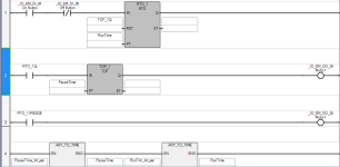
Perhaps this is the best answer (so far): it adds only two instruction to OP's original simple TONOFF approach, thus implementing what boils down to a State Coil/Fault Coil pattern (see here).

Caveat: the behavior is slightly different:

  1. the scheduled motor run time always expires with no delays;
  2. any extended motor run time occurs after the end of the scheduled time IFF the [Extend Run] input is 1 when the OFF timer expires;
  3. the [Extend Run] input has no effect before the OFF timer expires.
ccc.png
 
Last edited:

Similar Topics

I confess, I always have a little frustration trying to accomplish tasks in CCW that are simple in Studio 5000. My latest task is with timers...
Replies
5
Views
480
Hello, I am new to PLC programming. I just got an AB Micro810 with the CCW software. I am trying to create a timer that has an on time of 100ms...
Replies
8
Views
1,647
Hello, I am new on a forum. I have some problem with programming of PLC Micro850 which i can't figure with use of help in Connected Components...
Replies
5
Views
1,576
G'day guys, Just wondering is anyone could help me out with this one, i've done some plc programming before but never on CCW. Trying to knock up...
Replies
4
Views
2,774
I still have to preface this with "I am a newbie". Fumbling my way through ladder logic in Micro820 using CCW software. I need to send a 24vdc...
Replies
3
Views
2,538
Back
Top Bottom