You are using an out of date browser. It may not display this or other websites correctly.
You should upgrade or use an alternative browser.
You should upgrade or use an alternative browser.
Chemical dosing pump
- Thread starter koloyewo
- Start date
drbitboy
Lifetime Supporting Member
When I changed the NO of the counter to NC, it was working the other way round, so I change it back to the way it was,
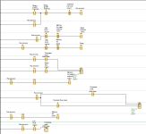
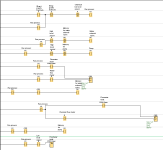
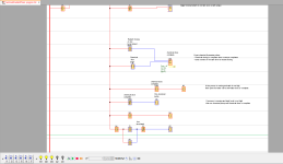
Ah, I see: you are inverting M2 and M3 (which effectively inverts C001 and C002, as I suggested) on the rungs feeding Q2 and Q3. If you replace M2 and M3 in those Break (NC) Contacts with C001 and C002, then you can eliminate the redundant --|C001|--(M2)-- and --|C002|--(M3)-- rungs. If you do not eliminate the redundant rungs, then you do not need to have the --|M1|-- Make Contacts on them.
From the attached image, the High level sensor is seen at the second rung, to stop both the water solenoid and the pump.
Ah: this is a different ladder logic diagram than the one for which you asked for help to check it.
drbitboy
Lifetime Supporting Member
drbitboy
Lifetime Supporting Member
drbitboy
Lifetime Supporting Member
@drbitboy, thank you for the feedback, all corrections have been made. But I am still unable to upload the program onto the plc controller (logo siemens). "showing it could connect to the remote device". Kindly help me on thi
I do not have a LOGO! and have never connected to one, hopefully someone else could help you with that.
You could also try searching the forum.
Thank you for the reply, I have been able to connect and uploaded the program to the PLC, it was tested, everything working fine except the flowmeter. While the fluid was running through the flowmeter, it was not sending any signal to the PLC, hence the input signal of the PLC could detect any pulse. Kindly find attached the datasheet of the flowmeter.
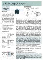

The output is open collector, (NpN) in other words it will not drive a PNP type input, if the PLC is capable of sink/source connection should be ok if connected properly, or you could try connecting a 4.7k resistor to the input to 24v but this may reduce the frequency it will work at.
I once did this when a replacement flowmeter was NPN rather than PNP, it worked but it is only a guess that 4.7k will switch the voltage above & below the switching points of the input, generally, inputs are 10ma if I remember correctly, the other thing is that the signal is effectively inverted i.e. input is on when no signal but should not matter.
I once did this when a replacement flowmeter was NPN rather than PNP, it worked but it is only a guess that 4.7k will switch the voltage above & below the switching points of the input, generally, inputs are 10ma if I remember correctly, the other thing is that the signal is effectively inverted i.e. input is on when no signal but should not matter.
Last edited:
Assuming you are using a PLC with PNP input i.e. 24v as a signal then as the output of the transistor in the flowmeter being NPN it actually pulses down i.e. sinks.
So use a pull up resistor connected as shown.
This gives 24v (well lower due to current being drawn by plc input but should be high enough to turn the input on, when the flowmeter turns on the output transistor in the flowmeter it drags the voltage down i.e. almost grounds it so the input to the plc goes low, it will depend on the input of the PLC but I believe a 4.7k resistor will allow enough voltage swing to stitch the input on & off.
normally you would use a flowmeter with PNP output that actually sources 24v via the emmiter of the FM output transistor
Shown is the output stage transistor of the flowmeter, this is connected to the PLC input (Source type) & the pull up resistor is connected to this & the supply.

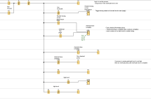
Hello guys, thank you for your continuous support. Concerning my chemical dosing pump project, I have had some issues, the flow meter for the water is not working so I tried to modify the program, now only to be controlled by the solenoid valve, and if the water reaches the high level sensor, the solenoid valve should stop, and when the water goes low past the low level sensor the system should start back again. But at the moment from the program (attached), when the water reached the high level sensor, it stops the solenoid valve and starts back again when the water goes below the solenoid valve. Please help me on this.

drbitboy
Lifetime Supporting Member
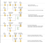
1) The Start-On-High-Level/Stop-On-Low-Level circuit is the same as the Start/Stop Circuit pattern that is writing a 1 or 0 to the M1 bit (cf. here).
1.1) So you want summat like this back of the envelope:2) I kept the "do it all on one rung" approach here, which saves instructions, but ...
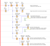
2.1) moving each of those branches hanging on the Run System logic to its own rung, also adding a Normally Open contact that examines M1 to each, will spread out the logic and make troubleshooting later (e.g. when a sensor or input channel fails) much easier, and that is where the real money is saved.
2.2) I.e. this
Last edited:
Similar Topics
We have a couple LMI chemical dosing pumps that are pumping caustic and sanitizer into a couple CIP tanks. I would like to know if there's a way...
- Replies
- 6
- Views
- 3,036
Hello,
I am relatively new to PLC's and water treatment. I currently working in a water treatment facility as an instrumentation worker. I have...
- Replies
- 1
- Views
- 2,093
Hello all,
I am working on Water treatement project i need to prepare logic for Dosing Pump
the system has two Dosing pump they having Storke &...
- Replies
- 7
- Views
- 2,812
Very interesting read and every WTP staffs nightmare. No one ever wants to end up on national news. Instrumentation work distracts staff and...
- Replies
- 12
- Views
- 5,676
We have a wash facility which uses a venturi to draw an iron phosphate chemical from a tank into a high pressure water line running at 160 bar...
- Replies
- 2
- Views
- 1,750


