Chemical dosing pump

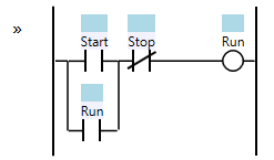
Looks to me like I3 (I believe, kind of hard to read) needs to go active to pull in Q2, which will then be "sealed in" by its own contact below I3. I only skimmed over the earlier posts so I'm not exactly sure what I3 is (high level?), but going on the red lines, it looks like it's active up to I3, and then the contact after it is highlighted red, which leads me to my conclusion that I3 didn't go active.
 
I3 is the high level sensor, when the water reaches I3, I want the I3 to stop Q2. When the water is going down, (you know I3 will change state) but I do not want that to affect Q2 by turning it on again, until it reaches I6 which is low level, and start the process all over again.
 
So when the water level is normal, or NOT high, is I3 active? I.e. is it normally closed and opens on high water level, or normally open and closes on high water level?
 
When water is normal or not high, I3 is NC or should remain active till the water is high, then I3 opens and stops Q2, when the water is going down, I3 should not have any effect on Q2 again, till the water goes to I6(low sensor), and start the process all over again
 
If I3 indeed opens when water level touches the sensor/switch, I think you need to change the instruction to be an NC instruction (examine if closed or XIC in Allen-Bradley speak), because currently in your screenshot I3 is not active, but if it's active when water is normal it would start the pump Q2 if programmed that way. I normally see high level switches (floats) as normally open when hanging and closed when floating in water.

EDIT: To clarify what I'm trying to say, if I3 is indeed active (as in the input is ON) when the water level is normal, your logic will attempt to start the pump when water level is high.
 
Last edited:
yes I3 is closed, and opens when water touches it, which closes the Q2, when water moves away from it, it changes state thereby opening Q2, and i dont want that to happen, when I3 is closed wehn water is going down it should not affect !3 again, that is my problem
 
Disregarding that the logic doesn't really seem to indicate it should work that way based on the action of the switch, if Q2 is turning on based on the status of I3, it should stay on until I6 drops out due to the seal-in around I3.
 
All i want is just to make I3 stop Q2 and not turn it back on


Do you want Q2 to stop (become 0) when I3 changes from 0 to 1 (i.e. when I3 is 1), or
do you want Q2 to stop (become 0) when I3 changes from 1 to 0 (i.e. when I3 is 0)?

What do you want to happen that makes Q2 become 1?

We still do not have an accurate and complete understanding of how this process is set up or what the control system is trying to achieve. Part of the problem is that, throughout this thread, the description of the process uses terms like open/close, active/inactive, up/down, above/below, and start/stop, and it uses those terms indiscriminately for pumps and valves and flows and level sensors. I do understand that, if there is a head or pressure difference (e.g. from a pump) in piping across a valve, then opening that valve when it was initially closed will start (allow) flow through that valve, and closing that valve when it was initially opened will stop (prevent) flow through a valve. And I understand that a valve can have stops on its positioning device (lever or stem or whatever). But I do not understand what it means to "stop a valve."
 
Last edited:
I am pretty sure that, in Post #29, I switched the logic

  • to write a 1 to the value of Q2 when the level is high (above the high level sensor), and
  • to write a 0 to the value of Q2 when the level is low (below the low level sensor),
  • and not change Q2 when the level is between the high and low level sensors.
The point is that, for the Start/Stop Circuit pattern,

  • the Start Condition is in parallel with the Run Seal-In Condition, and
  • the Stop (or Not-Stop) Condition is in series with the Start and Run Seal-In conditions.
Start-Stop-Circuit.png

What Start Condition, Stop Condition, and Run mean, and whether the ladder programm contacts are NO or NC, for your process will depend on the actual sensors and actual wiring of your actual process.

 
Hello guys, here is the over view of the project:

i1 = start push button

i2 = stop push button

i7 = chemical low level sensor

i6 = main tank low level sensor

i3 = main tank high level sensor

i4 = water flow pulse meter

Q1 = Chemical pump

Q2 = water solenoid valve

Now when start button is pressed, chemical pump should start and run till the set flow meter pulses reaches which is connected to a counter, the chemical pump stops and the water solenoid opens, and when the water reaches the high level tank, the high level sensor should stop the solenoid valve, when the water goes below the high level sensor, it should not turn on the solenoid valve. the process should stsrt again when the water reaches the low level sensor/
 
This was the initial program, but now the water flow meter is faulty, so I am modifying the program to work without the water flow meter

PLCtalk.PNG
 
We need more information. From the image logic and comments, the following ladder logic states are inferred for the inputs and outputs.

Note that the ladder logic sense (0 or 1) of level above and level below for the two low level sensors is different than that of the high level sensor. That said, 1 means high for high level sensor and 1 means low for the low level sensor.

Is this correct?
i1 = start push button: 0=>button is released; 1=>button is pressed

i2 = stop push button: 0=>button is released; 1=>button is pressed

i7 = chemical low level sensor: 0=>chemical level is not low, i.e. is above, this sensor; 1=>chemical level is low, i.e. is below, this sensor

i6 = main tank low level sensor: 0=>water level is not low, i.e. is above, this sensor; 1=>water level is low, i.e. is below, this sensor

i3 = main tank high level sensor: 0=>water level is not high, i.e. is below, this sensor; 1=>water level is high, i.e. is above, this sensor

i4 = water flow pulse meter: 0=>no pulse present; 1=>pulse present

Q1 = Chemical pump: 0=>do not run pump; 1=>run pump

Q2 = water solenoid valve: 0=>close valve (prevent flow); 1=>open valve (allow flow)
 
... the water flow meter is faulty, so I am modifying the program to work without the water flow meter

Then why are water flowmeter pulses accumulated by counter C002 "Water dose complete," and then that C002 "count complete" bit used to control Q2 (the water solenoid valve)?
 

Similar Topics

We have a couple LMI chemical dosing pumps that are pumping caustic and sanitizer into a couple CIP tanks. I would like to know if there's a way...
Replies
6
Views
3,036
Hello, I am relatively new to PLC's and water treatment. I currently working in a water treatment facility as an instrumentation worker. I have...
Replies
1
Views
2,093
Hello all, I am working on Water treatement project i need to prepare logic for Dosing Pump the system has two Dosing pump they having Storke &...
Replies
7
Views
2,812
Very interesting read and every WTP staffs nightmare. No one ever wants to end up on national news. Instrumentation work distracts staff and...
Replies
12
Views
5,676
We have a wash facility which uses a venturi to draw an iron phosphate chemical from a tank into a high pressure water line running at 160 bar...
Replies
2
Views
1,750
Back
Top Bottom