ClickPLC challenge

FrankBerends

Member
Join Date
Jan 2021
Location
Holland
Posts
9
Hi All,

Most of what I do in Click PLC is what I learned over here! But I'm running into a problem I just can't solve. I spend so much time on it and desperately now I fall back to you all...

I made two subroutines for my boat's windscreen wipers. Both routines work perfectly as long as I only use one of them. As soon as I make them both active in callable subroutines, one is working still fine and the other totally not. So it is something about blocking/not releasing the variables?

The functionality is as follows:
Ladder 1: This is just the port side wiper (there are 3 separately switched wipers). 1st push: Wiper speed 1 / 2nd push: wiper speed 2 / long push: wiper off ('parking')
Ladder 2: To simply switch on and off (speed 1 only) all 3 wipers together

Ladder two is still working if both subroutines are callable. Ladder 1 is only working when ladder 2 is not callable.

Can anyone point me in the right direction?

cheers
Frank
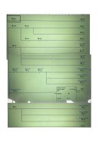
‎3 wipers on:off.‎1.jpg ‎PS Wiper speed 1 and 2.‎1.jpg
 
Are you writing to the same outputs in both subroutines? if so the last one called will win.
^ This.

TL;DR

Y305 and Y316 are both written to by -(OUT)- coil instructions in both subroutines; the only way the logic will yield the value you "want" from the earlier-called subroutine is if the later-called subroutine writes the same value as the earlier-called subroutine.

Coil instructions always write either a 1 or a 0 each time their rung is evaluated, whether the coil's input rung is True or False at the time the coil instruction is evaluated. So having a multiple coils write to the same memory bit (which includes discrete output bits) in a single program is considered a Bad Practice.

A rung in a subroutine is not evaluated unless that subroutine is called, which is why the first subroutine works as expected when the second subroutine is not called, and also why the first's results are overwritten when the second is called.

PLC programming is primarily about time, and the scan cycle is the clock, with the rung and branch evaluation precedence rule (left to right, top to bottom) determining the sequence of events.
 
Last edited:
Your best bet is to use internal markers in your routines then use those to drive the outputs, that way you can use those internal bits in combinational logic to turn on the outputs.
for example:
If you have internal bits i.e. 2 wiper speed 1 wiper speed 2 then if either of these bits are on disable the wiper speed 1 for all 3 wipers
Again simple logic
Here is one quick one I did.
Assumed if any wiper is running i.e. possible two speed then it disables the all wipers button, same goes in reverse i.e. if all wipers button pressed then it will not enable the individual ones, note I have used the button release pulse contact i.e. the mode becomes active when released so pressing a button & release before 2 secs sets either slspeed 1 or two (with 2 presses), a long press resets the bits
No idea what outputs you need but in my case used 2 outputs i.e. speed 1 & speed 2 but if you have just an output & an analog for speed it's still easy.
Haven't got klick at the moment but most of the functions are very similar I believe it has rising/falling edge contacts i.e. with ther up or down arrow in the contact.
 
Stealing @parky's idea to control and combine intermediate bits in local memory to drive each output in one place, with an alternate partition of state information, resulting in a cleaner, no-Set/Reset, coil-only approach for the individual wiper logic that will never restart the wipers if the PLC was last shutdown while the wipers were on.

Note the simpler and downright beautiful ;) flip-flop logic to toggle between speeds 1 and 2 using an XOR circuit clocked by the wiper pushbutton release event (edge).

Also, the All-3 pushbutton press will

  • EITHER turn off all three wipers when all were running at speed 1 before the pushbutton press, even if all wipers were set to speed 1 via the individual (port, amidship, starboard) pushbuttons,
  • OR set all wipers to run at speed 1 for all other configurations (on, off, or speed) before the pushbutton press.
I also built this and tested it using the Do-More simulator.

Caveats


  • This is what I would do if I knew I would be the only person who would ever be doing troubleshooting on this system, because I would recognize the patterns involved, even a few months down the road.If you cannot easily understand how and why this works, then you will be better off with @parky's approach, which is simpler to follow.
  • Since digital input edge detectors are in play, it might be worthwhile to implement debounce logic, to ensure multiple edges are not generated by operators executing single presses and releases.
 
Last edited:
LOL, giving that most programmers seem reluctant to use set/reset bits here is my modified one with no resets. There could be other fubctionality i.e. use All wipers button held down to reset all modes but that is not something I would do but others may like it. I have not included debounce timers found in the past it is not that important on something like wiper control, perhaps a machine yes but hey it is a set of wipers,
 
Guys, you are all very helpful, thanks!
Now I'll have to study it all in detail over the weekend. As DRBITBOY says, I will not implement anything I don't thoroughly understand myself.
Looking forward to lay this puzzle!
 
Yes I suggest you study what has been posted, although very similar slightly different approaches, things to bear in mind, the use of negative edge triggers off the pushbuttons (Falling edge trigger) makes it easier to implement, also a lot relies on the way the PLC scans so in effect we use this to stop double triggering i.e. setting speed 1 but next scan it will not set speed 2
You will notice that the speed 2 rung is before the first speed rung, this is important as the negative edge trigger from the button is only on for one scan so because on the start of scan speed 1 bit is not on as an interlock for speed 2 so it will not trigger speed2, then speed 1 is latched in, on next scan the button trigger will be off so it requires 2 pushes of the button to enable speed 2. this approach is often used to give once only operation, very much like creating a shift register you shift backwards in other words on a shift pulse you copy n-1 to n by starting at n = say 20. I have assumed that the speed bits just enable different outputs but it is also possible to move a value into an analogue for speed on those bits if that was required.
 
You will notice that the speed 2 rung is before the first speed rung, this is important as the negative edge trigger from the button is only on for one scan so because on the start of scan speed 1 bit is not on as an interlock for speed 2 so it will not trigger speed2, then speed 1 is latched in, on next scan the button trigger will be off so it requires 2 pushes of the button to enable speed 2. ...


^ This. PLC programming is about time with the scan cycle as the clock: detecting when events happen; remembering what the state was on the previous scan(s); choosing when to respond to those states and their changes by assigning output values.

In my code I realized that if any of the wipers are at speed 2 and the operator pushes the All-3 button, which will turn on all wipers at speed 1, then, at the end of the scan cycle when the rising edge of that All-3 edge is detected, those wipers at speed 2 will have values of 1 in both speed 2 and speed 1 outputs. It is corrected on the next scan cycle, but it is a bug. That is easily remedied by adding a resets of the speed 2 outputs where the speed 1 outputs are set, or by the other remedy which is to simply move the All-3 response rung to be the first rung in the program, and then code hanging the Start/Stop Circuit pattern rung will write 0s to the speed 2 outputs.

In the Patterns of Ladder Logic Programming pages, here, there are many patterns that experienced programmers recognize. One pattern that could be added is the one-shot, also known as edge detection.
 
I made two subroutines for my boat's windscreen wipers. Both routines work perfectly as long as I only use one of them. As soon as I make them both active in callable subroutines, one is working still fine and the other totally not. So it is something about blocking/not releasing the variables?

This may be totally off base, but from the language used here (e.g. "callable subroutines" and "releasing the variables"), I suspect you are experienced in "normal" programming languages (Python, Perl, C/C++, Java/Script, Fortran, etc.).

If my suspicion is correct, then you may not understand the PLC scan cycle. The best explanation I have seen is the first few videos in forum member @Ron Beaufort's boot camp videos here. That video, plus the patterns webpages mentioned earlier, cover about half of what is needed to know to write PLC programs. Of course, connecting PLCs to hardware and managing communication is a much bigger topic than programming, and programming is probalby the smallest, least-interesting part, but it sounds like you have the rest covered at least for the current project.

One analogy for understanding the PLC scan cycle is the GAWK (AWK) program, with which you may be familiar: each line read, parsed, tokenized, and passed by the GAWK executive to the user's GAWK program is analogous to the input hardware states being read into memory at the start of a PLC scan cycle.

Anyway, if you are thinking about PLC programs from a procedural programming standpoint, you will always be struggling, so I strongly suggest trying to clear your head of that and watching Ron's videos before doing anything else. Each is less than a dozen minutes long and the whole series takes less than two hours, and you may need to watch some sections repeatedly to get it, but at around 20-30 minutes I suspect the light bulb will come on and you will never look back.
 
@Parky: I like the straightforward approach, but I’m a bit puzzled about the ‘pulse’ (rung 10).
I can’t find that in my Click PLC
Possible to replace with On-delay and Off-delay timers? And how long should that pulse be?
Or is it maybe just a bit i can set/reset?
 
@Parky: I like the straightforward approach, but I’m a bit puzzled about the ‘pulse’ (rung 10).
I can’t find that in my Click PLC
Possible to replace with On-delay and Off-delay timers? And how long should that pulse be?
Or is it maybe just a bit i can set/reset?

A 'pulse' has many names: one-shot; edge detector. A pulse instruction generates a 1 or Rung-is-True output for exactly one scan cycle when boolean its operand transitions from 0 to 1, and does not generate another 1 or Rung-is-True output until its boolean operand has both returned back to 0 and made another transition to 1.

In Click the instructions look summat like these: -|v|-; -|^|-; i.e. contacts with up or down arrows in them.

On- and Off-delay timers cannot be used to implement them, because there could be multiple scan cycles while the timer is timing.

The logic of a pulse instruction is the equivalent of the following, where everything in bold blue is encapsulated within a single -|^|- instruction:
Code:
[B][COLOR=#0000ff]     INP           MEM[/COLOR][/B]     OUT
[B][COLOR=#0000ff]-----] [------+----]/[[/COLOR][/B]-----( )----
[COLOR=#0000ff][B]              |[/B][/COLOR]
[COLOR=#0000ff][B]              |    MEM[/B][/COLOR]
[COLOR=#0000ff][B]              +----( )------[/B][/COLOR]
 
DR: is right, you cannot use the pulse input contacts directly in the logic so create the logic DR: has shown in place of the Pulse output rung then use that in the next rung.
 

Similar Topics

I intend to use a clickPLC to turn a motor on and off for predetermined times. I am still very new to this and not sure exactly how I wire...
Replies
3
Views
1,536
I've run into a non-plc issue that is proving hard to solve. I'm designing a mechanical device that has a base/foundation that must satisfy the...
Replies
3
Views
401
Hi experts, I hope you're all having fantastic days. I'm having trouble getting my CompactLogix 1769-L24ER to communicate with my InTouch...
Replies
13
Views
1,021
Hi everyone, I am working as a technician at a automotive factory. Recently, we had same quality problem several times on a workpiece. I had a...
Replies
12
Views
1,486
The objective: Reach about 10’ horizontally into a 1300F furnace, and pick up a 140lb rectangular container, then pull the container back out of...
Replies
15
Views
1,874
Back
Top Bottom