Code Sequence

Fiona

Member
Join Date
Apr 2004
Posts
14
Hi. This is my first post.

The answer to this is probably really simple but it's really bothering me.

why scan a step sequence in reverse order?
ie if there are ten steps in a motion sequence what is the benefit of scanning step 10 first then step 9 and so on?

Fiona
 
Last edited:
hello and welcome,

How about ...

If you had to stop the sequence half way through because of a jam or something and needed to back track to remove the problem or something.

Cheers,


F
 
Why in reverse order

It's one way to ensure that the step is active for at least one whole scan.

It depends on the sequencer, and exactly how the programmer programmed it, of course, but sometimes conditions are true to go both from step 4-to-5 and from 5-to-6 durning the same scan. By scanning 5-to-6 first, the 4-to-5 rung will leave you on step 5 for the one scan. This may make other code make false the transition conditions for 5-to-6, or may capture data needed for some future step. If they are scanned in order, you could go directly from step 4 to step 6 in two rungs, and the rest of the logic would never see that you were on step 5.

There are other, perhaps better, techniques to accomplish the same thing, but this is generally why some programmers do it. They may have even learned to do it this way, and so follow it, without knowing why, or without even needing to in this particular project. Old habits can die hard.
 
Hi Guys

Thanks for your help. It has had me puzzled for a while now.

Allen, I think you are right this particular programmer has been taught to program in this manner and uses it without knowing exactly why (or perhaps he knows why but he finds it easier to program this way). Because the sequence is a series of SR flip flops step 2 sets step 3 and resets step 1 etc. there is no need to guard against setting outputs from more than one step.

Fiona.
 
I've used this method to sequentially pick logic routines. A little over simplified:
|Start Something|----(Start One Shot)
|Start One Shot|---|/C|---|B|---|A|-----(Set C)
|Start One Shot|---[/B]---|A|---------(Set B)
|Start One Shot|---|/A|-----------(Set A)


If you tried this in ABC instead of CBA order they would all start the same scan instead of picking one.

As others pointed out this is not necessarily the best way, but it is simple and works as well.
 
One possible better method and comment

See the example in Hugh Jack's book. His method separates the state machine into two parts. A part that determines what state is is to be executed and a part that actually execute the state. This will not suffer from synchronization/race problems.

The problem with relying on the order of the states is that one can't back step reliably although it does work while the states are executed in the right order.

Consider this folks. Just about routine you need for a PLC has already been done before. Why re-invent the wheel? Unfortunately that is done way too often and is costs big $$$$$. THIS IS ONE OF THE BIG FAILURES WHEN IT COMES TO PLCS!!! I see people struggling with ASCII to floating point routines and such. There should be organized PLC user groups. I don't see this anywhere. How much is a reliable general case state machine in ladder worth?
 
Peter...I can only agree wholeheartdely. Personally I am happy to contribute as best I can to the various FAQ's people ask for, but every now and then there is an interesting PROGRAMMING thread ...and that is why I am here...to learn new ideas, or to see old problems in a new light.

Terry...K-Maps are wonderful things, but I have only once used them in anger to organise all the possible switching paths that two mains, two generators and a bus coupler MCB's could navigate. At first I thought the task trivial, then I realised it was potentially very large, and finally I devised a neat k-map scheme that more or less saved the day.

Care to share with a little more about how you implement them?

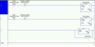
But to keep on topic, here is the standard way to do a reliable, general state case machine (for just two states) in ControlLogix. The key is that the State word is not decoded until the end of the state sequence, so the Step < word.bit> is not updated until at least one whole program scan is completed. This prevents the problem Allen descibes.

state.jpg
 
Last edited:
Hello.

This really is a great site I didn't expect as much assistance when I posted my question.

hopefully I can clarify a couple of things,

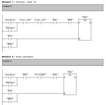
as the code attached shows the sequence is purely sequential so Karnaugh maps won't be any help but if the code depended on combinational logic then yes Karnaugh maps could be used to simplify the truth table.

As each step of the sequence is a latched contact that is only reset when the subsequent step is reached then I think that the code can be re-written to scan from step 0 to step n without any ill effects. As the sequence can only ever be on one step at any time.

But I think scanning the steps from last to first the way this code is written will add to the scan time.

P.S. "step 52" follows "step 42" in the sequence


Fiona

sequence.jpg
 
Last edited:
Fiona-
Unless you add a jump or branch command after the current active step or do something else to get out of your state machine (similar to a break in C), the order of the state selection rungs won't have an effect on the scan time. You will stall scan all the rungs. sequentially.
Some plcs will only evaluate a rung up to the first false series instruction it encounters. At that point it would skip to the output and act accordingly. If your plc is one of these and you are worried about scan time lead all your rungs with the state contact. This will provide the plc with a false series condition immediately on all rungs except for the rung containing the current active state.

Peter-
The mechanics of developing a state machine is not the difficult part. Deciding where to transition is. That is where a state machine will hang if it is going to. And no matter how elegant the base state driver is it will still hang if not told to transition correctly. Now, granted, we as plc programmers do rebuild code more often than we should. But if library functions were the only thing that made a programming form stable then C programs should have stopped hanging 15 years ago.

Keith
 
Fiona,
If you look closely at the sequence of your code you will see that on the first scan:
Line one will not be true because line 2 is not yet true.
line two will turn true in this scan.
On the second scan:
Line two will now turn true.
This may have effects elsewhere in the program depending on how those outputs are used. If you reverse the lines the first scan:
Line one (was line two) will turn true.
Based on the now true output of line one line two (formerly line one) will also turn true eliminating the state where "41" is true and "42" is false.

Once you get to thinking sequentially this is easy but until then it can be very confusing. Think:
1. Read physical inputs
2. Run through code line by line
3. Write Physical outputs
It's oversimplified but it helps.
 
What about the others?

kamenges said:
Peter-
The mechanics of developing a state machine is not the difficult part. Deciding where to transition is. That is where a state machine will hang if it is going to. And no matter how elegant the base state driver is it will still hang if not told to transition correctly. Now, granted, we as plc programmers do rebuild code more often than we should. But if library functions were the only thing that made a programming form stable then C programs should have stopped hanging 15 years ago.

Keith

Maybe writing a state machine is not difficult for you, but what about the others? For them example state machines would be very helpful. Hanging transitions is not the biggest problem, it is the race conditions and synchronization problems. At least with a well organized state machine one can tell exactly what transition is hung up and what code must be changed to make the machine work properly.
 
I've made a crude state machine before in GE Fanuc using a counter. You could troubleshoot by looking at the incoming conditions and you could move a value into the counter at any time to force the machine into a specific part of the sequence. I don't know how useful this technique is with other machines, it wouldn't be near as simple with Siemens I know.
 
K-Maps...

A properly designed/utilized K-Map is perfectly well suited for describing a sequence.

A properly designed/utilized K-Map will provide all of the "dynamic" information that any sequential or non-sequential process could require.

I have pre-printed K-Maps in various sizes:
  • 2 x 1
  • 2 x 2
  • 3 x 2
  • 3 x 3
  • 4 x 3
  • 4 x 4

Granted, increasing the number of elements in a K-Map can very quickly make the process of addressing each particular combination very tedious.

However, this problem can be minimized quite handily if "Modularization" is properly applied to a process. Sadly, too many people do not understand the concept or process of "modularizing".

When asked about modules in their process, some people look at everything on the network (plant-wide) and determine that they have a half-dozen machines on the network and therefore a half-dozen modules.

That would usually be wrong.

Certainly, there a half-dozen machines. But how many "modules" exist within each machine?

Oh... In Machine-1 there is a Loader, a Cutter, an Unloader, a Stacker and a Wrapper. There must be five "modules" in that machine.

This is where a mild "curve-ball" comes in.

Are there any "modules" in the Loader?
How does the Loader obtain material to load?
Once obtained, how does the Loader load the Cutter?
After loading the Cutter, what does the Loader do?

There are many "modules" in any process, and usually, more modules than initially thought. That is, if one gives some real, carefully considered thought to a process, one can usually find that there are many more... OK, here's the real "curve-ball", "sub-modules" within "modules".

The whole idea behind "modularization" is to determine the smallest, complete set of Inputs and Outputs and "Conceptual-Conditions" necessary to perform a particular action.

The concept behind "modularization" is to "granulize" the process. That is, work with the smallest functional-chunck and then pass information to the next functional-chunck until the material is ready to move to the next larger module.

Communication between functional-chuncks occurs by means of "flags".

Typically, in well designed programs, material is passed "on-demand". A subsequent-module issues a "call" for material from a previous-module. That is, material is not passed to the following module unless the following module is "calling" for material to be passed.

This follows the "Demand-Side Economic Model".

The alternative is the "Supply-Side Economic Model" where material is shoved down your throat... as in, "Here it comes, I hope you can handle it!"

So... back to K-Maps...

In terms of real modularity, K-Maps can usually be made fairly small; my usual worst-case is 4 x 4. That is not to say that I usually run into 4 x 4 but that I don't usually run into anything worse than 4 x 4.

Now, in those rare cases where the need goes beyond 4 x 4 onto 4 x 5, I simply use one more pre-printed sheet to address the additional case of Element-X. I then identify the first sheet as Element-X = False and the second sheet as Element-X = True. The K-Map then goes beyond two-dimensional into three-dimenensional.

I have never not been able to modularize to less then 10 Elements. If you find that you can not modularize a portion of the process to less than 10-elements then you are probably not looking very closely.

Just for the exercise, K-Maps can be expanded to an unlimitied number of multiple-dimensions. You can look at those various dimensions as sheets within folders, folders within a drawer, drawers within a cabinet, cabinets within an office, etc., etc., ... ad infininitum.

Any particular set of elements can be a set of steps in a sequential process.

All you need to do is carefully develop the procession through the various steps; much like we already do in automation programming.

BTW (By-the-Way), for those that like to use the term "state-machines", typical state-machines, and I really mean "typical", as in the way that most people develop "state-machines", do NOT cover all cases... that is why some supposed "state-machines" hang.

State-Machines are based on the same logic that a K-Map uses! You are bound to a "HANG" if your State Machine Logic translates into a crappy (ambiguous) K-Map!

(466)
 
Last edited:
Terry, you would love programming FPGAs.

The only problem is that the development software optimizes the code for you so you don't need to know karnaugh maps. ( Everyone but Terry cheers!! beerchug ). Now why doesn't PLC development software optimize ladders? :unsure:

BTW, you are not done describing how the K maps are used to make a state machine. Inquiring minds want to know. Yes, I know. I am just bugging Terry for raising the subject of using Karnaugh maps to make state machines because he hasn't told everyone how it is done.

You are on the spot Professor Terry. 👨🏻‍🏫
 

Similar Topics

(subtitle: should I bother with structured text? AKA: Panasonic FP gurus please contact me.) Newbie question, but hope someone can help me...
Replies
12
Views
8,576
Anyone have some code I can use for refrigerant Compressors Sequence Control IE an example Cascade Sequencers The simplest sequencers use a...
Replies
3
Views
2,064
Hello, I am trying to read a barcode scanner input using a cognex dataman 280 barcode reader, store it another string, the compare with another...
Replies
0
Views
26
Hi there, I'm new to plc programming and was wondering why I get this error code when I run my simulation for these temperature sensors? What I'm...
Replies
2
Views
69
Hi All, Someone at work has put a PLC system on my desk, that's just been taken off an idle production line. He said "It's an S7 PLC. We don't...
Replies
10
Views
279
Back
Top Bottom