Compressor Start Sequencer

Here is my attempt at this problem (RSLogix: .RSS; .pdf); I think it is equivalent, if not identical, to what Tom suggested.

The last two rungs of the MAIN LADder Program File, with six instructions each, implement the desired sequencing.


TL;DR


The MAIN LADder file has three rungs:

  • One rung to get the COMMAND via a subroutine call (JSR)
  • Two rungs to implement the sequencing
The sequencing logic uses three INTegers:
  1. NEXT_ON - index of next compressor to start
  2. NEXT_OFF - index of next compressor to stop
  3. COMMANDED_ON - bit mask of commanded states of the three compressors
The MAIN code ensures that any commands either to stop when all three compressors are already off, or to start when all three are already on, do nothing.

The first rung MAIN ladder logic calls the COMMANDING subroutine, which puts one of three values in INTeger COMMAND:

  • 0 - do nothing
  • 1 - stop a compressor
  • 2 - start a compressor
The COMMANDING subroutine examines the pressure and other states to set COMMAND. COMMANDING implements all of the "If pressure is less than 300psi ...; if pressure is greater than 400psi for five minutes... " logic, and sets COMMAND to one of those values based on that logic. COMMANDING will issue a [do nothing] COMMAND for 10s after any compressor is commanded to start.


The MODEL_STI routine models (simulates) the process pressure in response both to the number of compressors running, and to whether the "machine" is running. MODEL_STI runs on interrupts at 200ms intervals. MODEL_STI is pure fiction of course but its behavior is similar enough to the process described by the OP that it can show how the MAIN sequencing algorithm would work.
 
Hi Drbitboy, post a pdf I would like to see it, I do like your thoughts


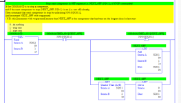
I think there is a PDF in the .zip ... yup, but the guts of the sequence logic are below for the STOP command; the logic for the START command is essentially the same.


I am pretty sure it is only one possible implementation of Tom's Lead/Lag/Standby approach.


INTeger COMMAND is the input: 0=do nothing; 1=STOP; 2=START.


INTeger NEXT_OFF is the index of the next compressor to turn off: 0 or 1 or 2.


INTeger COMMAND_ON is a bitmask; bit COMMAND_ON/[NEXT_OFF] is the {0:OFF,1:ON} state of compressor NEXT_OFF.

xxx.png
 
Last edited:
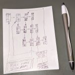
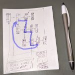
Here is the state diagram with all possible transitions: each enclosing rectangle is a state; each arrow is a transition; arrows to the right represent starting compressor NEXT_ON; arrows starting down or up represent stopping compressor NEXT_OFF. The left-middle column in each state rectangle has the indices of the of the compressors that are off; the right-middle column has the indices of the compressors that are on.


Note that if you start at wherever index 0 is and go up to the top of that column, then from there to the bottom of the other column, and then up through that other column, the order of indices will always be [0,1,2].


Also note that if COMMANDED_ON (bottom box in each state rectangle rectangle) is 0 (all off) or 7 (all on), then the NEXT_ON and NEXT_OFF index (two numbers in top side-by-side boxes in each state rectangle) will be the same, and the only way to tell if compressor NEXT_ON can be started is to check the current state of that compressor via bit COMMANDED_ON/[NEXT_ON], and similarly for stopping compressor NEXT_OFF.


Visualising these states and transitions are what made me realize the the FIFO approach, while workable, was a more complex solution than warranted by the problem.

IMG_20200424_150351.jpg
 
Last edited:
Hi.

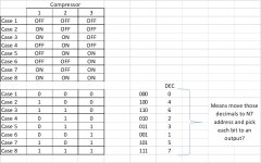
To me states are:


Then when pressure is below 300 PSI move 0 to N7:10
When pressure up to 350 PSI move 6 to N7:10
When pressure up to 400 PSI move 4 to N7:10
and so on

Picture1.jpg
 
Here is a rough & ready bit of code (note: I only have GX Works & TIA) at the moment. This uses a sequencer to process the steps. I tried to use pulse timers to inhibit motors starting until 10 sec after a stop, but noticed one minor problem that a motor may start at the same time as one other stopping, probably not a problem but you could add timers on the motor run rungs, however, on steps 1 to 3 this would double the time. The code after the motor outputs is purely for simulation of the pressure rising & falling, not tested fully as I kept getting disturbed but from what I saw it seems to be reasonable.
Yes there may be a few minor issues but cannot be a***d to test it fully and is only an idea to consider, the other half has to work being a key worker and she makes sure I have a list of jobs to do while she is at work. :mad:
 
The example on the last page is more for general sequencing or rotation of motors (in this case compressor pumps will refer to pumps from here on) based on duty for at least 2 pumps running dependent on press/vac.(only had a quick look so may not have got the complete picture), however, from the OP's post on here it does seem rather than having duty selection is not what the truth table shows, it appears the poster wants 3 pumps to run in that particular sequence given the pressure setpoints. so as to rotate the pumps, I do not agree in whole to this so many questions 10 second delays is short for many large compressors on starts per hour, and depending on the rate of medium being consumed the pumps could cycle quite quickly however, that is pure conjecture. in Ron's post a number of people have suggested a sequencer of some description i.e. counter etc. Yes there are many ways to skin a cat. bit sequencers, word sequencers & shift registers etc. Many systems I have seen use 2 duty 1 standby and inverter controlled to ramp rather than on off but that is more recent, can't imagine many new system not using that sort of control. this ensures a constant pressure or vacuum supply. This does look more like an assignment or an upgrade rather than an actual new system.
 
There is several ways of code this.
Ron have example on this thread for 3 pumps and 3 vacuum swithes


http://www.plctalk.net/qanda/showthread.php?t=9499&page=5
(reading still from page 1 is useful)


Nice!


TL;DR


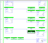
I think* Ron's ladder in that PDF needs to do the equivalent of [repeating Rungs [0004:0005] after Rung 0006], to cover the case where N7:0 is incremented to 3 by Rung 0001 but bit PUMP_C_BYPASSED is 1. However that would not work as it violates the [don't set a bit in more than one rung/branch] rule.


One approach (out of MANY) would be to OR (put in parallel) two new branches:

  • EQU(N7:0,3) AND PUMP_C_BYPASSED
  • EQU(N7:0,2) AND PUMP_B_BYPASSED AND PUMP_C_BYPASSED

with the [GEQ(N7:0,4)] on Rung 0002.


* That said, as the code is now, all three A/B/C_IS_1ST_PUMP bits would be off for only one scan, so maybe it does not matter and that was intentional.


Implemented that sequencer to confirm this; see below.

xxx.png
 

Attachments

  • sequencer_3_pumps_with_bypass.zip
    286.8 KB · Views: 8
Last edited:

Similar Topics

I Am looking to get ahold of the modbus map for an air compressor. I HAve emailed the vendor as well, just wondering if any of my friends here...
Replies
1
Views
117
Got a customer with a Chinese air compressor, 240V, 15HP. The present control of the entire system is inside their VFD. It controls the motor...
Replies
2
Views
1,053
Hey All, I've got a Sullair LS-16 (V160) compressor with the 3-line Supervisor controller (identical to this...
Replies
9
Views
2,466
Hi folks, i'm pretty much new on this topic and i need some help with the dual compressor part 3 and 4, currently working on part 3 i cant make...
Replies
20
Views
5,131
Hi everyone, Working on a project that has 2 Metering Pumps that are Pneumatically actuated. I need to add an Air Compressor to the system and I...
Replies
10
Views
1,898
Back
Top Bottom