Constant Force Application, Getting Started

atoledob

Member
Join Date
Aug 2023
Location
California
Posts
7
Hello all, this is my first time working with a PLC and dealing with hardware, so please have patience with me.

I have an electric rod-style actuator driven by a rotary servo motor and a servo drive. The actuator will exert force on a platform that can slide up and down. The goal is always to maintain constant force applied onto the platform. I connected a load cell in line with the direction of force transmission between the end of the actuator and the platform surface (i.e., the load cell is sandwiched between both surfaces). Additionally, I purchased a load cell amplifier that can condition the 2 mV/V load cell signal into 0-5 V/RS485 output. Ultimately, the goal is to achieve force control via the PID functions available within the S7-1200 PLC. At the end of a test, I want the actuator to return to the initial position and zero torque (tare).

Here are the specific products I am using:

The servo drive has options for Torque control mode, Torque/Speed control mode, and Torque/Position control mode. I believe that I can accomplish my tasks with just the Torque control mode. From the attachment, I plan to use the following digital inputs EM2 (forced stop - decelerates the motor to a stop), SON (servo on), RES (reset any alarms), RS1 (forward rotation), and RS2 (reverse rotation). I will have ALM (alerts a malfunction) and RD (alerts system is ready to operate) for the digital outputs. I bought all the necessary pushbuttons, selector switches, and e-stop for these digital inputs and outputs.

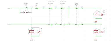
A 50-pin pigtail connector will interface the servo drive and PLC. I have provided my attempt at a wiring diagram. Some specific confusions/questions are:
  1. Should the e-stop be wired to a DI or 24 VDC? I’ve seen two wiring diagrams with both cases.
  2. My interpretation of shorting the unused analog inputs of the CPU is to jumper the inputs in X11 and connect them to 0 VDC. Is this correct? The CPU manual doesn’t have any details.
  3. I plan to power the CPU using a bulky lab-grade linear DC-regulated power supply (0-30 [VDC], 0-5 [A]). I calculated the power budget and found that I need a power output of >= 12 [W] and a current output >= 0.46 [A]. Should I stick with this PSU or use a switching power supply (maybe a class 2 PSU that plugs into a wall socket)?
  4. I’ve read in other discussion threads that I should not connect my load cell to the AI of the CPU because it only provides 10 bits which is far too low resolution. Would you recommend I purchase an extra AI signal board/module that allows for 12, 13, or even 16-bit capabilities?
  5. From the Torque wiring diagram, I think I also need to use the TC (analog torque command of +/- 8V) and wire it to an analog output of the CPU (I would have to purchase an AO module too). So, the load cell is connected to an AI and sends the PLC the force value. The PID loop uses the force setpoint to calculate the updated force value. Then, I will have to multiply this force value by an acting distance to get torque, and, lastly, scale it to +/- 8 V to send back to the servo drive. Am I thinking about this correctly?
Getting the hardware configured is the first step. Hopefully, I am heading in the right direction. Any feedback will be much appreciated. Thank you.

My files are too big to upload, so please access the files on this Google Drive link.
 
The goal is always to maintain constant force applied onto the platform.
This will be a problem. To keep the force constant you need to keep the torque constant. The problem occurs when the actuator starts moving/accelerating. It will keep accelerating as long as you maintain the constant torque/force. Eventually you will hit the end of travel abruptly. That is why there is a torque/speed limit mode but now torque is reduced to just that necessary to overcome gravity and friction but this will maintain a constant velocity. You should also have ramps.

You are right about not having enough resolution with only 10 bits. A problem I have seen with analog load cell amplifiers is noise and/or a slow response with the noise is filtered out.
 
  1. Should the e-stop be wired to a DI or 24 VDC? I’ve seen two wiring diagrams with both cases.
  2. My interpretation of shorting the unused analog inputs of the CPU is to jumper the inputs in X11 and connect them to 0 VDC. Is this correct? The CPU manual doesn’t have any details.
  3. I plan to power the CPU using a bulky lab-grade linear DC-regulated power supply (0-30 [VDC], 0-5 [A]). I calculated the power budget and found that I need a power output of >= 12 [W] and a current output >= 0.46 [A]. Should I stick with this PSU or use a switching power supply (maybe a class 2 PSU that plugs into a wall socket)?
  4. I’ve read in other discussion threads that I should not connect my load cell to the AI of the CPU because it only provides 10 bits which is far too low resolution. Would you recommend I purchase an extra AI signal board/module that allows for 12, 13, or even 16-bit capabilities?
  5. From the Torque wiring diagram, I think I also need to use the TC (analog torque command of +/- 8V) and wire it to an analog output of the CPU (I would have to purchase an AO module too). So, the load cell is connected to an AI and sends the PLC the force value. The PID loop uses the force setpoint to calculate the updated force value. Then, I will have to multiply this force value by an acting distance to get torque, and, lastly, scale it to +/- 8 V to send back to the servo drive. Am I thinking about this correctly?


1) E-stop is/should be a safety mechanism that removes all energy from the aparatus. Solid-state inputs should only be used to inform the program of the e-stop status.


2) Yes. Or you will see noise on these inputs.


3) Wherever I have analog signals, I gravitate toward linear.


4) Is the load-cell even necessary? Not possible to calibrate the torque command? Typically, one would use the Torque-Limit.


If PID_Output > Torque_Limit then PID_Output = Torque_Limit


Resolution: Rarely specified is the fact that the vast majority of servo-drives, resolve their analog commands to 12bits (unless this has changed recently) and this is bi-polar, so effectively +/- 11bits. I couldn't find the Mitsubishi spec.


I have used Torque-mode, exclusively for 30+ years now. I have many axes that position the work-piece and then push it to assist the metal-forming process (40HP drive).


Craig
 
Last edited:
4) Is the load-cell even necessary?
It depends on the require accuracy. Also the torque applied at the motor = torque applied at the load - torque due to friction - torque due to gravity.
It isn't clear if the force must be kept constant going up and down.

Not possible to calibrate the torque command?
Probably but then see above. The OP can't simply use the motor torque.

Typically, one would use the Torque-Limit.
Craig
This depends on the answer to the previous questions
 
My random thought on using motor torque is that it's a valid option...but...as Peter said the motor's torque includes friction in the actuating mechanism and in whatever's supporting the platform. And that *will* change over time. Most likely a fairly short time in my experience unless you're in a very clean lab environment. If you need an accurate force, you'll need to either re-calibrate frequently to re-characterize the applied-force-to-motor-torque relationship or just use a load cell continuously. If it matters a lot, I would probably just use the load cell.
 
1) E-stop is/should be a safety mechanism that removes all energy from the aparatus. Solid-state inputs should only be used to inform the program of the e-stop status.


There ARE safety rated PLCs (including a 1200F you could use instead with failsafe IO cards), where you would wire it directly in. Sounds like that might be overkill for your situation though.


Usually, you don't JUST use the estop straight controlling the 24V, because then the power immediately comes back on when you release the button. I usually see safety relays (when there isn't a safety PLC) to allow you to switch higher voltages/amperages and also to handle the required reset behavior and diagnostics. Then the PLC monitors the status of the safety relay to know when it's OK to control the process.
 
Forced-contact relays are not much more costly than standard but buy a big-name, brightly colored box with "safety" stamped on it and your bank-account will take a hit.

basic safety.PNG
 
Hello all. Thank you for your responses. Hopefully, this clarifies some of your questions:

It isn't clear if the force must be kept constant going up and down.
Look at this image to help visualize what I am saying. The platform will want to push back onto the actuator because the material I am studying tends to expand in volume when compressed. So, the force will need to remain constant as the actuator pushes down onto the platform and as the actuator is pushed back by the platform. So, I suppose force must be kept constant going up and down.

1) Is the load-cell even necessary?
I believe the load cell is necessary to ensure that the force I want to be applied is what I tell it to be. Eventually, I will have to run models of this experiment, and I need faithful results from my experiments to tune my models.
Also, I couldn’t find the analog command resolution values in the manual for the servo drive. The only information it has is that the position encoder resolution is 22 bits and that analog speed command has 14 bits resolution, but can be increased to 16 bits by changing a parameter.

It will keep accelerating as long as you maintain the constant torque/force. Eventually you will hit the end of travel abruptly. That is why there is a torque/speed limit mode …. A problem I have seen with analog load cell amplifiers is noise and/or a slow response with the noise is filtered out.
So, is using the Torque/Speed control mode the better way to approach this problem?
Also, would the noise issue be resolved if, instead of sending analog signals to the PLC, I transmit the load cell values to the PLC using RS485 and MODBUS? I’ve never used MODBUS before (and I’m pretty sure I have to pay extra for it in the Siemens software), but if it means better results, I wouldn’t mind going down that route.

Usually, you don't JUST use the estop straight controlling the 24V, because then the power immediately comes back on when you release the button.
That is a good point. I saw a video on YouTube where they use a safety relay in addition to two NC contactors. Should I do something similar? There aren’t any specific safety levels I need to achieve.
 
Hello all. Thank you for your responses. Hopefully, this clarifies some of your questions:


Look at this image to help visualize what I am saying. The platform will want to push back onto the actuator because the material I am studying tends to expand in volume when compressed. So, the force will need to remain constant as the actuator pushes down onto the platform and as the actuator is pushed back by the platform. So, I suppose force must be kept constant going up and down.


I believe the load cell is necessary to ensure that the force I want to be applied is what I tell it to be. Eventually, I will have to run models of this experiment, and I need faithful results from my experiments to tune my models.
Also, I couldn’t find the analog command resolution values in the manual for the servo drive. The only information it has is that the position encoder resolution is 22 bits and that analog speed command has 14 bits resolution, but can be increased to 16 bits by changing a parameter.


So, is using the Torque/Speed control mode the better way to approach this problem?
Also, would the noise issue be resolved if, instead of sending analog signals to the PLC, I transmit the load cell values to the PLC using RS485 and MODBUS? I’ve never used MODBUS before (and I’m pretty sure I have to pay extra for it in the Siemens software), but if it means better results, I wouldn’t mind going down that route.


That is a good point. I saw a video on YouTube where they use a safety relay in addition to two NC contactors. Should I do something similar? There aren’t any specific safety levels I need to achieve.


First coffee of the day so I might be off-track here but it seems to me that all you need to do is close the position loop and apply some integral. I'm reading that the actuator is merely required to hold its ground as it encounters increased push-back?


That's some encoder resolution...Nice! But the command resolution isn't going to provide any increase in current-output resolution. It's like an on-off light-switch where you might be able to physically move the actuator in an analog fashion but the light is only going to be either on or off.


Lousy 6:30am analogy, sorry :ROFLMAO:


Craig
 
Last edited:
Look at this image to help visualize what I am saying. The platform will want to push back onto the actuator because the material I am studying tends to expand in volume when compressed. So, the force will need to remain constant as the actuator pushes down onto the platform and as the actuator is pushed back by the platform. So, I suppose force must be kept constant going up and down.
This simplifies things because the actuator doesn't need to move freely. It is just supplying an opposing torque/force. Torque/force control or torque/force limit will do

I believe the load cell is necessary to ensure that the force I want to be applied is what I tell it to be.
Yes, but that means you are really using a force limit.

So, is using the Torque/Speed control mode the better way to approach this problem?
No! Not from your latest post. The question I have is how does the cycle start? Do you need to move the actuator until it hits what is expanding or does the actuator just sit until the material expands to hit the actuator? You probably don't want to use force control until contact is made and then enable force control. Otherwise the actuator will rush down because it sees no opposing force.

Also, would the noise issue be resolved if, instead of sending analog signals to the PLC, I transmit the load cell values to the PLC using RS485 and MODBUS?
DON'T USE MODBUS! It isn't fast enough or reliable enough. RS485 is best. Just hope the inputs to the S7-1200 are fast enough

I could set this up in no time but I wouldn't use an S7. The S7 may not be fast enough. A lot depends on how compliant the expanding material is. However, it probably is compliant enough where tuning shouldn't be too difficult.

Forces can change quite a bit very rapidly. This is why fast sample and update times are necessary. For instance, how much will the force increase per mm of expansion and how fast per second? These are thing you need to know.
 
Just hope the inputs to the S7-1200 are fast enough

I could set this up in no time but I wouldn't use an S7. The S7 may not be fast enough.


I'm a fan of S7, and even I'm a bit nervous about this on a 1200. You can do a whole lot in a 1200 for the sub $1000 price, but I've never thought of high speed motion as being on the list.


It might happen to work, but that's pretty far from will definitely work.
 
I'm a fan of S7, and even I'm a bit nervous about this on a 1200. You can do a whole lot in a 1200 for the sub $1000 price, but I've never thought of high speed motion as being on the list.


It might happen to work, but that's pretty far from will definitely work.


In the Mitsubishi manual under "How To Use The Program"


These drives are programmable and we know that they have analog inputs. Wouldn't be suprised if it could handle the whole thing.


Craig
 
In the Mitsubishi manual under "How To Use The Program"

These drives are programmable and we know that they have analog inputs. Wouldn't be suprised if it could handle the whole thing.

Craig
Yes, motion controller tend to leave PLCs in the dust for moving things or controlling forces.

There is a lot more to this than slapping a bunch of control on this. One needs to know about what is being compressed because that makes a huge difference. Compressing marsh mellows is much different than compressing silicon rubber to make power line isolators.
 
The question I have is how does the cycle start? Do you need to move the actuator until it hits what is expanding or does the actuator just sit until the material expands to hit the actuator?.

Sorry, I should have been more clear before. The actuator, load cell, and platform are all joined together. So, they move together as one unit. The triangle wedge you see in the video is to allow for uniform force transmission all the way from the platform onto the shear cell (the deforming square you see moving).

Initially, the actuator is in a starting position such that it is imposing zero stress (everything is in equilibrium). Then, the actuator will press down onto the platform with a desired force value. Then, the shear cell starts moving right, then left, and finally back to the initial starting position. During this time, you see the actuator moving up and down to accommodate the moving platform. As the actuator moves up and down, I want it to maintain the force value that I am imposing.

One needs to know about what is being compressed because that makes a huge difference. Compressing marsh mellows is much different than compressing silicon rubber to make power line isolators.

The shear cell will be packed with Teflon cylinders. These are pretty rigid, so you won’t get that much deformation. A previous student who did similar experiments found that the distance the platform pushes back (the delta L_y from my past response) varies between 9.9 mm to 24 mm (~ 0.4 to 0.95 in).

DON'T USE MODBUS! It isn't fast enough or reliable enough. RS485 is best. Just hope the inputs to the S7-1200 are fast enough…Forces can change quite a bit very rapidly. This is why fast sample and update times are necessary. For instance, how much will the force increase per mm of expansion and how fast per second? These are thing you need to know.

When you say RS485 is best, are you referring to using serial communication? The baud rate specs for an RS485 communications module/board are: 300 baud, 600 baud, 1.2 kbits, 2.4 kbits, 4.8 kbits, 9.6 kbits (default), 19.2 kbits, 38.4 kbits, 57.6 kbits, 76.8 kbits, 115.2 kbits.

I did some rough calculations, so I’m not sure how correct they are, but force changes about 0.16 [N/s] and about 0.37 [N/mm].


If the load-cell is deemed to be necessary, I wouldn't discount the analog signal.
The good news (if I actually have the correct Mitsubishi manual) is that the analog input can be configured to 16bit.
This will almost certainly be a differential input and as long as good wiring practice is followed, noise shouldn't be an issue.
There is also the 4-20mA analog option which is current-driven and less sensitive to noise.


The 4-20mA can be converted to 0-10v right at the drive's analog input.


Attached is a snippet from what I believe to be the correct manual.


Craig

analog_input.PNG
 
Last edited:

Similar Topics

I am new to using Functional Block Diagram (FDB) language programming in CCW. I want to set a variable to a constant if a contact is closed...
Replies
7
Views
416
Hello, I have posed a similar question before, but the DB then provided me with pre-allocated "spares". In this instance I need to declare a...
Replies
13
Views
4,129
Hello gentlemen, Why does this work: VAR CONSTANT SIZE_OF_dutEVENT : UDINT := SIZEOF (DUT_Event); MAX_SIZE_OF_dutEVENT : UDINT := 5...
Replies
2
Views
1,608
Hi! I know there is a lot of skilled people with Schneider somachine in this forum, so i have to ask something. How and why do you use constant...
Replies
4
Views
2,207
Hello everyone, Who knows how to implement constants in CASE loop via address to do it flexible. I show it on screenshot. Thanks a lot.
Replies
53
Views
15,802
Back
Top Bottom