Converting 4-20mA signal to 0-10VDC

neilm

Member
Join Date
Feb 2019
Location
Jackman
Posts
28
Hello everyone,

I don't have much of an electrical background and so I have these questions:
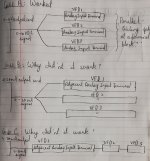
Please check the attachments. I have 4 cases where a reference signal is used to control 3 VFDs at their respective analog and common terminals of Yaskawa drive.
1Q) Can someone please help me explain why Cases B and C didn't work even though I changed the VFD parameters?
2Q) Will Case D work?

Pic1.jpg Pic2.jpg
 
Last edited:
A lot of VFD's have, sometimes hidden under a comm's module or cover, a switch to cut in a shunt resistor for the mA setting. Even if the parameter is changed, the physical wiring does not unless the switch is moved.

PowerFlex series are on the control circuit board and visible if you look up.

Sew Eurodrive locates them under the removable Ethernet port. (at least on the ones I work on)
 
Case A, Voltage at paraller. OK


Case B, milliamps at paraller. Can't work never.


Case C. milliamps at series. Should work, but you need connect last VFDs mA- connector to supplying 0VDC on supply side.


Problems can also be that mA outputs are usually limited for max. 500ohm resistance, 3 VFD's and long mA cables can have more. Also some drives have dip switches for selecting mA and V.


Case D.
Can't work. resistor on series with VFD's not change 4-20mA to 0-10V.
You should connect 500ohm resistor's one leg to 0VDC and another to mA source, then you have on mA side 2-10Volts reference which you can connect to 2-10 input. Better still to use signal conditioner.
 
Lare nailed it - wire your 4-20 in series

Source + --> VFD 1 signal +
VFD 1 Signal - ---> VFD 2 Signal +
VFD 2 Signal - ---> VFD 3 Signal +
VFD 3 Signal - ---> Source -
 
Hey Altezza, we tried doing that, checked the mA across the terminals of each VFD and were getting the correct mA (as compared to code) but the VFD's U1-16/17 (The parameter which shows the received % mA at the T14) was showing 0, so we decided to stick to the Voltage terminal.
 
The thing is initially they were signalled by a 0-10V signal from a PLC. Later we ended up changing the source PLC and that has only 4-20mA output card and its module capacity on the chassis is full. We did try the series connection and measured everything with a multimeter. It did seem fine but the VFD simply wasn't showing any indication of receiving the signal. That's why this is my last resort to add a resistor or signal conditioner.
 
The thing is initially they were signalled by a 0-10V signal from a PLC. Later we ended up changing the source PLC and that has only 4-20mA output card and its module capacity on the chassis is full. We did try the series connection and measured everything with a multimeter. It did seem fine but the VFD simply wasn't showing any indication of receiving the signal. That's why this is my last resort to add a resistor or signal conditioner.


mA connection should work, especially if you see with mA meter on series that there is correct mA.
Sounds like that there is some settings needed still on VFD side.
Signal condiotioner is easier, sinvce you can change 4-20mA to 0-10 volts with some of them. Then you don't need reconfigure nothing on VFD side.
 
As mentioned above Yaskawa Drives have a selector switch for Voltage or Current Inputs. If it doesn't match your input it will not work.
 
Case A
Case A can work because voltages can be paralleled and if the inputs are high enough resistance, then there is little loss in the signal.

Case B
Case B does not work (and will never work) because 4-20mA is known as a current loop, which like in all electrical circuits, the current must flow all the way through the loop for it to be a current loop. Your wiring attempts to create 3 loops from a single source and the source cannot regulate the current to three loads.

Case C
Case C appears to be a series loop, where there is one loop where the source current passes through three different analog inputs in series.

If wired properly: output (+) to 1st (+), 1st (-) to 2nd (+), 2nd (-) to 3rd (+), 3rd (-) to output (-), it might work, but the probability is low.

The output must be capable of driving the combined input resistances for all three VFDs. The output is spec'd in terms of how much resistance it can drive and the analog inputs have a spec'd input resistance. It's your job to look those numbers up and see if the the source can drive the drive the total load.

And the inputs must be floating or isolated and not grounded. Otherwise grounding issues add or subtract current from the loop and the result is chaos. This happens all the time. Most inputs are not designed to be run in 4-20mA loop series circuits.

There are splitters that take in one 4-20mA and provide two 4-20mA outputs.

Case D
Case D will not work as drawn, but could with modification.

The 500 ohm resistor must be across the source 4-20mA (+) and (-) terminals.

Then the (+) and (-) terminals are run to each of the VFD voltage inputs (like your Case A)

The voltage will be 2-10Vdc for a 4-20mA signal. If you can configure the 4-20mA signal for 0-20ma, then the voltage will be 0-10Vdc. Sometimes, the scaling on the VFD voltage input can be adjusted to 2-10Vdc.
 
If changing a Yaskawa VFD from original voltage input to new current input, there are both DIP switch and parameter changes required. The picture example attached is for a small V1000. You will need to consult the manual for your drive to confirm switch location and parameter selection. You may also need to use terminal A2 instead of A1.

yaskawa analog.PNG
 

Similar Topics

I have an actuator, Belimo cat.# AFB24-SR, that has 2...10VDC control input and feedback output signals. However, in their spec sheet, they say...
Replies
5
Views
6,323
Hi Guys, I was assigned a task to use the percentage setpoint on the HMI to have an output equivalent to 4-20ma using GE Fanuc 9070. If you have...
Replies
4
Views
2,243
Hi Has anyone try to convert 1-5Vdc to 4-20mA by putting 250 ohms resistor? I simply relied on the basic OHM'S law: V = IR 5V = 20mA (R) R...
Replies
22
Views
22,869
Good Morning Everybody I am wondering if there is a way to convert a 0-5v / 0-10v to a 4-20ma signal. This will help me make a decision on the...
Replies
5
Views
4,294
Hello everyone, can anyone help me with covert the STL code to ladder. Iam using plc s71200. A %DB1.DBX33.7 // angel of vaccum...
Replies
2
Views
208
Back
Top Bottom